Check patentability & draft patents in minutes with Patsnap Eureka AI!

Control system and method for brake bleeding

a control system and brake bleeding technology, applied in the field of automatic systems, can solve the problems of increased cost relative to automated systems, increased risks of human operators taking place in rail yards, and increased risks of human operators using rail yards

Active Publication Date: 2018-02-27
GE GLOBAL SOURCING LLC
View PDF16 Cites 3 Cited by
  • Summary
  • Abstract
  • Description
  • Claims
  • Application Information

AI Technical Summary

Benefits of technology

The system efficiently and accurately bleeds air brakes with reduced first attempt failures and time consumption, ensuring precise control and validation of the brake release process, even with initial perception errors, and can adapt to different vehicle configurations.

Problems solved by technology

Use of human operators in a rail yard, however, is not without problems.
The operations taking place in a rail yard pose safety risks to the human operators.
Additionally, the use of human operators can involve increased cost relative to automated systems.
But, automated systems pose problems as well.
Although applicant is unaware of any automated system that can bleed air brakes of a vehicle, such an automated system that pulls on a brake lever to disengage a brake system may be unreliable due to the wide variances in the brake systems among several different vehicles.
For example, different vehicles may have brake levers in different locations that may be difficult for the automated system to locate, may have brake levers that require different amounts of force to actuate, may have other components that block movement of the automated system when attempting to access and pull the brake lever, may have brake levers that become temporarily stuck, etc.
These variances can make it difficult for an automated system to perform brake bleeding operations.

Method used


Image

  • Control system and method for brake bleeding
  • Control system and method for brake bleeding
  • Control system and method for brake bleeding

Examples


Embodiment Construction

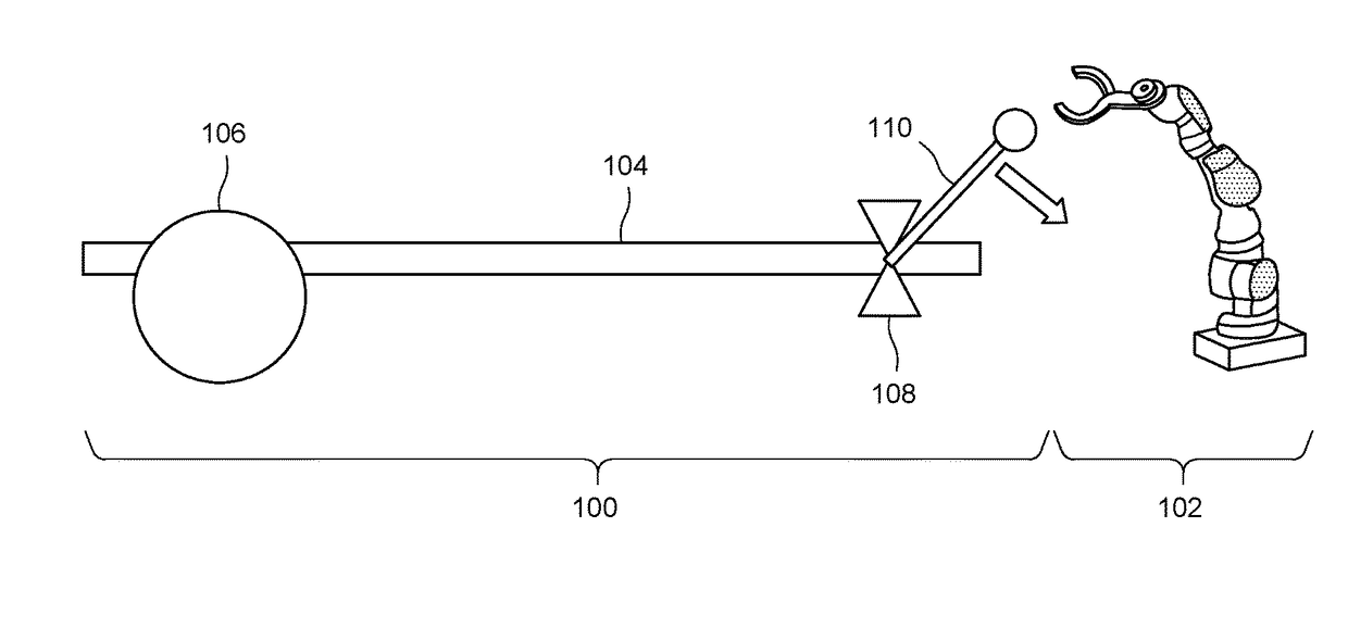
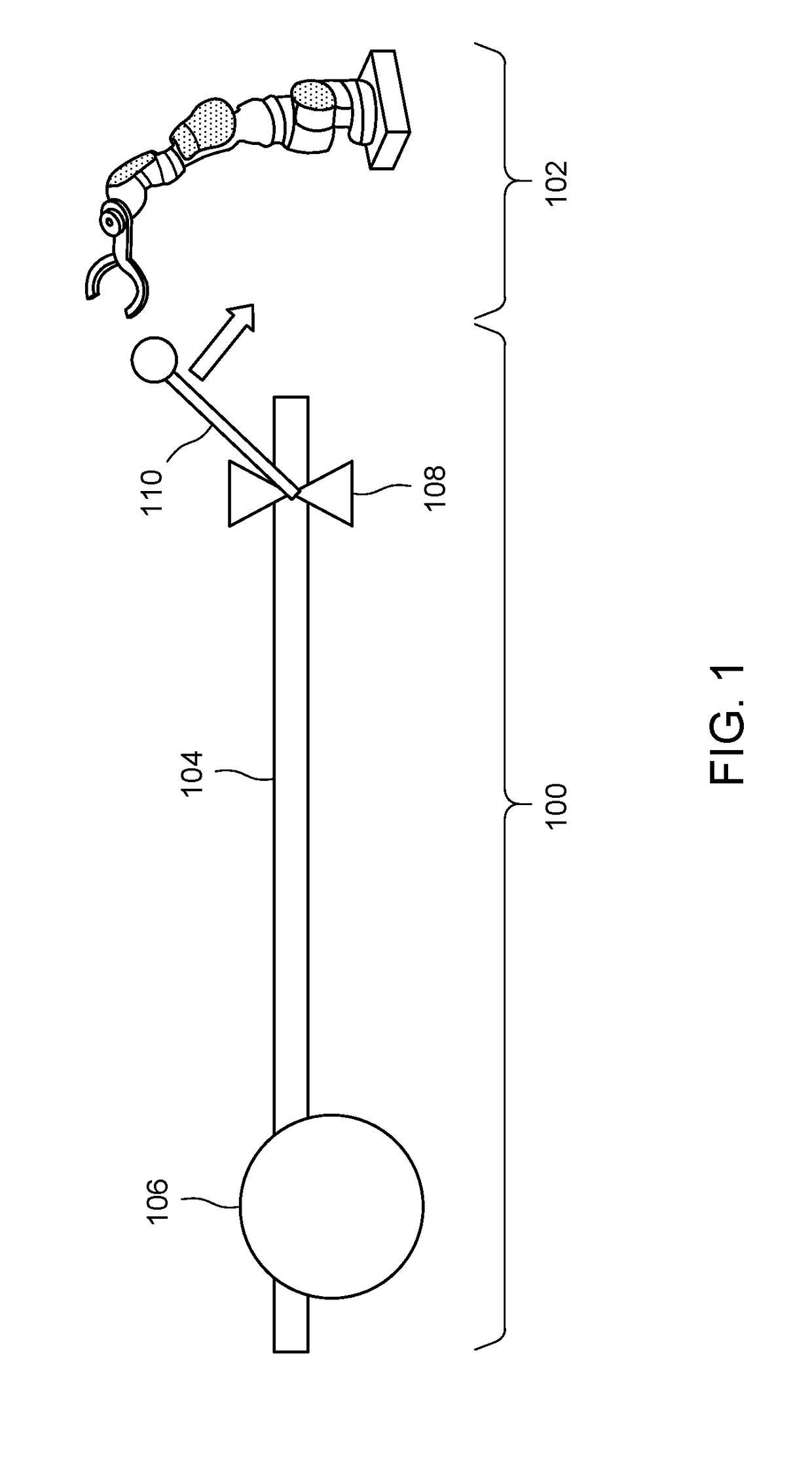
[0014]Reference will be made below in detail to example embodiments of the inventive subject matter, examples of which are illustrated in the accompanying drawings. Wherever possible, the same reference numerals used throughout the drawings refer to the same or like parts. Although embodiments of the inventive subject matter are described with respect to vehicles and vehicle systems such as trains, locomotives, and other rail vehicles, embodiments of the inventive subject matter are also applicable for use with vehicles generally, such as off-highway vehicles (e.g., vehicles that are not designed or permitted to travel on public roadways), agricultural vehicles, and / or transportation vehicles, each of which may include a brake system.

[0015]The act of bleeding a brake system, also referred to herein as brake bleeding, using an automated system may risk substantial detection errors for the automated system to locate and then actuate the target object, which may be a brake lever. For e...


PUM


Abstract

A system is provided that includes a machine assembly, a first imaging sensor, an encoder, and one or more processors. The machine assembly is movable to actuate a brake lever of a vehicle in order to open a valve of an air brake system. The first imaging sensor is positioned to acquire two-dimensional perception information of a working environment that includes the brake lever during movement of the machine assembly towards the brake lever. The encoder detects a displacement of the machine assembly relative to a reference position of the machine assembly. The one or more processors estimate a target position of the brake lever relative to the machine assembly during movement of the machine assembly based on the two-dimensional perception information and the displacement. The one or more processors drive the movement of the machine assembly towards the target position of the brake lever.

Description

CROSS-REFERENCE TO RELATED APPLICATIONS[0001]This application claims priority to U.S. Provisional Application 62 / 269,523; 62 / 269,425; 62 / 269,377; and 62 / 269,481, all of which were filed on 18 Dec. 2015, and the entire disclosures of which are incorporated herein by reference.FIELD[0002]The subject matter described herein relates to automated systems that bleed brakes of a vehicle, such as air brakes of a vehicle.BACKGROUND[0003]Some vehicles include brake systems that operate based on pressure differentials in fluid disposed in the brake systems. For example, air brakes in some vehicles (e.g., rail vehicles) may disengage when the air pressure in the air brakes is decreased. The air brakes in such vehicles may be released in certain environments in order to perform operations on the vehicles. The air brakes in rail vehicles, for example, may be disengaged while in a rail yard in order to more freely roll the rail vehicles around within the rail yard.[0004]In order to disengage the a...

Claims


Application Information

Patent Timeline
Patent Type & Authority Patents(United States)
IPC IPC(8): G06F19/00B60T15/04B25J11/00B60T7/16B25J19/02B25J13/08G06T7/00H04N5/225H04N7/18B25J9/16B60T15/54
CPCG06T7/70B25J9/162B25J9/1612B25J9/1661B25J9/1664B25J9/1694B25J11/00B25J13/085B25J19/021B25J19/023B60T7/16B60T15/048B60T15/54H04N5/2253H04N7/181B25J9/1697Y10S901/01B25J9/1666B25J9/1679G05B2219/40039G05B2219/40586G05B2219/40613B25J13/003H04N23/54
Inventor TAN, HUANLIZZI, JOHN MICHAELFORMAN, DOUGLASTHEURER, CHARLES BURTONAL ASSAD, OMARPATRICK, ROMANOKANNAN, BALAJEEGEFEN, YONATAN
Owner GE GLOBAL SOURCING LLC
Features
  • R&D
  • Intellectual Property
  • Life Sciences
  • Materials
  • Tech Scout
  • Unparalleled Data Quality
  • Higher Quality Content
  • 60% Fewer Hallucinations
Learn More