
Linkage press machine

a press machine and linkage technology, applied in the field of press machines, can solve the problems of reducing durability, reducing the durability of conventional presses, and requiring custom, and therefore expensive, parts for prior crankshafts and sector gear mechanisms, and achieving the effect of reducing the cost of manufacturing the present machin

Active Publication Date: 2018-03-06
BTM COMPANY
View PDF35 Cites 1 Cited by
  • Summary
  • Abstract
  • Description
  • Claims
  • Application Information

AI Technical Summary

Benefits of technology

[0006]The present linkage press machine is advantageous over conventional presses. For example, the present machine operates faster and smoother. Furthermore, standard components can be used to move the present ram, as compared to traditional devices, thereby reducing the expense of manufacturing the present machine. Additional advantages and features of the present machine will become apparent from the following description and appended claims.

Problems solved by technology

These conventional presses, however, suffer various deficiencies.
Furthermore, traditional hydraulically and motor driven presses often have jerky opening and closing movements which reduces durability.
Prior crankshaft and sector gear mechanisms also require custom, and therefore expensive, parts.

Method used


Image

  • Linkage press machine
  • Linkage press machine
  • Linkage press machine

Examples


first embodiment

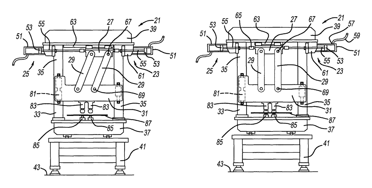
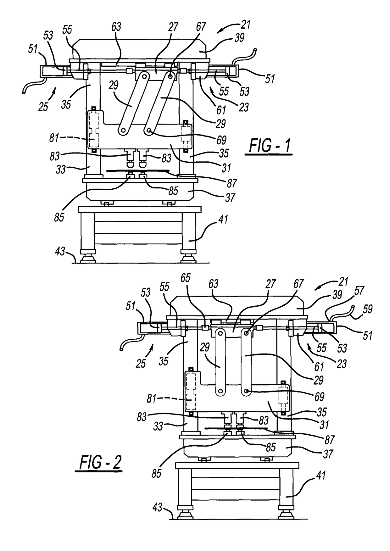
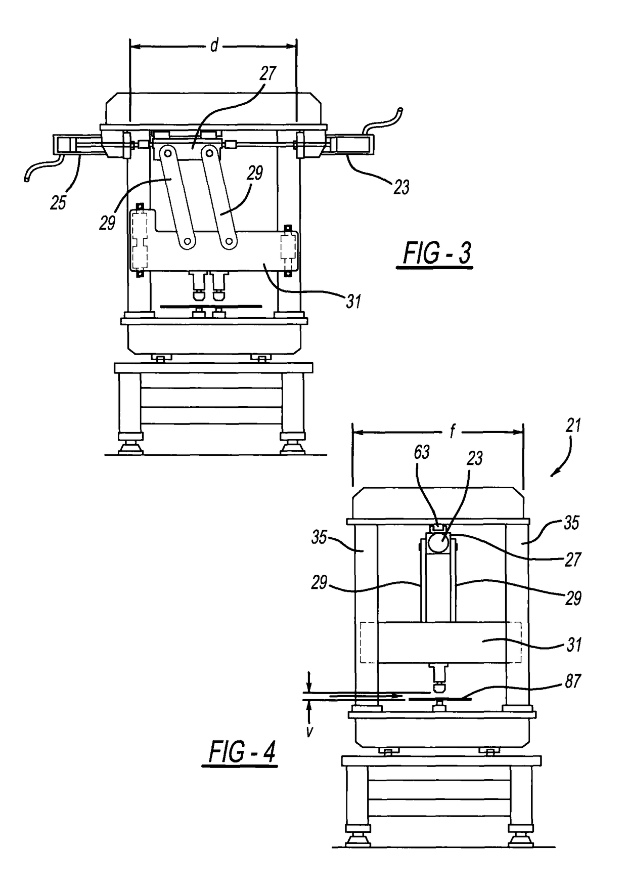
[0020]a linkage press machine 21 is illustrated in FIGS. 1-4. Machine 21 includes a pair of coaxially aligned fluid-powered actuators 23 and 25, a carriage or slide 27, linkages 29, a ram 31 (also known as a die) and a stationary structure 33. Structure 33 includes four spaced apart corner posts or frames 35 affixed to and spanning between a base 37 and a cap 39. Optionally, a table or support 41 is located between base 37 and a factory floor 43. Adjacent pairs of frames 35 define four generally vertical planes surrounding a periphery of machine 21. Optionally, protective covers may be externally attached to frames 35, in which event, they define the vertical planes. A workpiece feeding direction dimension f is less than a perpendicular dimension d for machine 21.

[0021]Each actuator 23 and 25 includes a fluid powered cylinder 51, a piston 53 and a piston rod 55. Hydraulic or pneumatic fluid is pumped into each cylinder at an inlet port 57, via a hose 59, which pushes pistons 53 and ...

second embodiment

[0030]A second embodiment linkage press machine 101 can be observed in FIGS. 6-13. This exemplary machine includes an upstanding tool body 103, a base 105 affixed to the body 103, a box-like tool support 107 mounted to the tool body opposite base 105, an actuator 109 coupled to the support 107, and a transmission mechanism driven by the actuator 109. The transmission mechanism includes a jackscrew 121, a ball or nut 123, a carriage or slide 125, and one or more linkages 127 (two parallel linkages being shown).

[0031]Jackscrew 121 is coupled for rotation with an output shaft 129 of actuator 109, which is a servomotor including a rotating armature therein. Jackscrew 121 is held within support 107 by a pair of downwardly extending brackets 131 with internally affixed support bearings 133. Nut 123 has an internal thread which is enmeshed with a helical external thread of jackscrew 121. Flanges of nut 123 are attached to a back edge of carriage 125 by way of screws. An oversized bore 135 ...


PUM

PropertyMeasurementUnit
vertical distanceaaaaaaaaaa
dimensionaaaaaaaaaa

Abstract

A press machine includes at least one actuator and at least one linkage to open and close a ram. Another aspect employs a sheet metal-working punch mounted to the ram. A fluid-powered piston drives a carriage coupled to a linkage in another aspect of the present machine. In still another aspect, at least a majority of an actuator is located externally to an outside surface of a stationary structure within which a ram is located. Yet a further aspect both opens and closes a ram with a unidirection movement of an actuator.

Description

CROSS-REFERENCE TO RELATED APPLICATIONS[0001]This application claims the benefit of U.S. Provisional Application No. 62 / 259,697, filed Nov. 25, 2015, which is incorporated by reference herein.BACKGROUND AND SUMMARY[0002]The present invention relates generally to press machines and more particularly to a linkage operated press.[0003]Presses for stamping and piercing sheet metal are well known. Conventional presses typically are driven by a large hydraulic piston, vertically oriented screws rotated by electric motors, or crankshafts, in combination with toggle linkage mechanisms. Examples of these conventional presses are disclosed in the following U.S. Pat. No. 7,810,368 entitled “Multi-Mode Hammering Machine” which issued to Rusch on Oct. 12, 2010; U.S. Pat. No. 6,510,786 entitled “Hydromechanical Press Drive” which issued to Harsch on Jan. 28, 2003; U.S. Pat. No. 4,920,782 entitled “Press Drive” which issued to Hellwig on May 1, 1990; and U.S. Pat. No. 3,763,690 entitled “Press Bra...

Claims


Application Information

Patent Timeline
Patent Type & Authority Patents(United States)
IPC IPC(8): B21D5/02B21D5/01B21J7/02B21J7/32
CPCB21J7/32B21J7/02B21D5/02B21D5/01B21D28/002B30B1/008
Inventor FAITEL, WILLIAM M.
Owner BTM COMPANY
Learn More