Use of a feed-through for installation in a wall or floor element

a technology for installing walls and floor elements, applied in pipes/joints/fittings, forms/shuttering/falseworks, pipes, etc., can solve problems such as unintended water entering and propagating along the outside of tube elements

Active Publication Date: 2018-03-06
HAUFF TECHN
View PDF20 Cites 0 Cited by
  • Summary
  • Abstract
  • Description
  • Claims
  • Application Information

AI Technical Summary

Benefits of technology

[0007]The locking device can also improve the handling of the duct, for instance when the latter is mounted at a formwork. Then, for instance, one end of the tube element can be mounted at a formwork member and the length of the tube element can be adjusted thereafter and locked, wherein the duct is more or less stable even before being fixed to the opposing formwork member. The tube element pieces do not slip with respect to each other so that the risk of one of them dropping down and being damaged is reduced.
[0023]In another preferred embodiment, the locking ring guided on the outside of the second tube element piece can be brought into the locking position by just moving it in the line direction (thus, no screwing movement of which only a component of motion is directed in the line direction is required). This can simplify the handling and also the design of the locking ring; also in view of the cost, a simple, closed ring extending continuously in the circumferential direction can be preferred.
[0027]For improving this movability further, a transition region between a respective tensioning tongue and the remaining tube element piece, which can act as a hinge to some extent, can also be provided with a reduced wall thickness. The wall thickness taken in the distance direction can for instance be reduced by a groove extending in the circumferential direction, preferably a groove arranged on the inside of the tube element piece.
[0030]In a preferred embodiment, the displaceability of the locking ring (independently whether screwable or displaceable by a movement in the line direction only) is limited by a stop, for instance a stop provided at the end of the second tube element; for instance a flange projecting outwardly can be provided (not necessarily circumferentially). In the end position, the tensioning can be maximal as well, for instance due to a sloped outer surface of the second tube element piece as described above. For a fitter, the stop can indicate a reliable locking.
[0031]A preferred embodiment of a second tube element piece in which a first one is guided displaceably relates to a second tube element piece partitioned into a tube section and a contact section being one-piece with the latter. The tube section is made of a rather stiff synthetic material which can for instance withstand the forces occurring during the casting in concrete and which in general shows rather no deformation upon the application of a force. By providing for the contact section a material softer in comparison to the material of the tube element, a good sealing contact between the second and the first tube element piece can be reached nevertheless and for instance water propagating along the outside of the tube element can be prevented from entering.

Problems solved by technology

For instance, a duct being only adjustable in length can be disadvantageous, because significant forces can act on the tube element during the casting in concrete; without a locking device, the tube element pieces can be displaced with respect to each other unintendedly which can result in a leakage finally.
Later on, water can propagate along the outside of the tube element for instance and enter unintendedly.

Method used


Image

  • Use of a feed-through for installation in a wall or floor element
  • Use of a feed-through for installation in a wall or floor element
  • Use of a feed-through for installation in a wall or floor element

Examples


Embodiment Construction

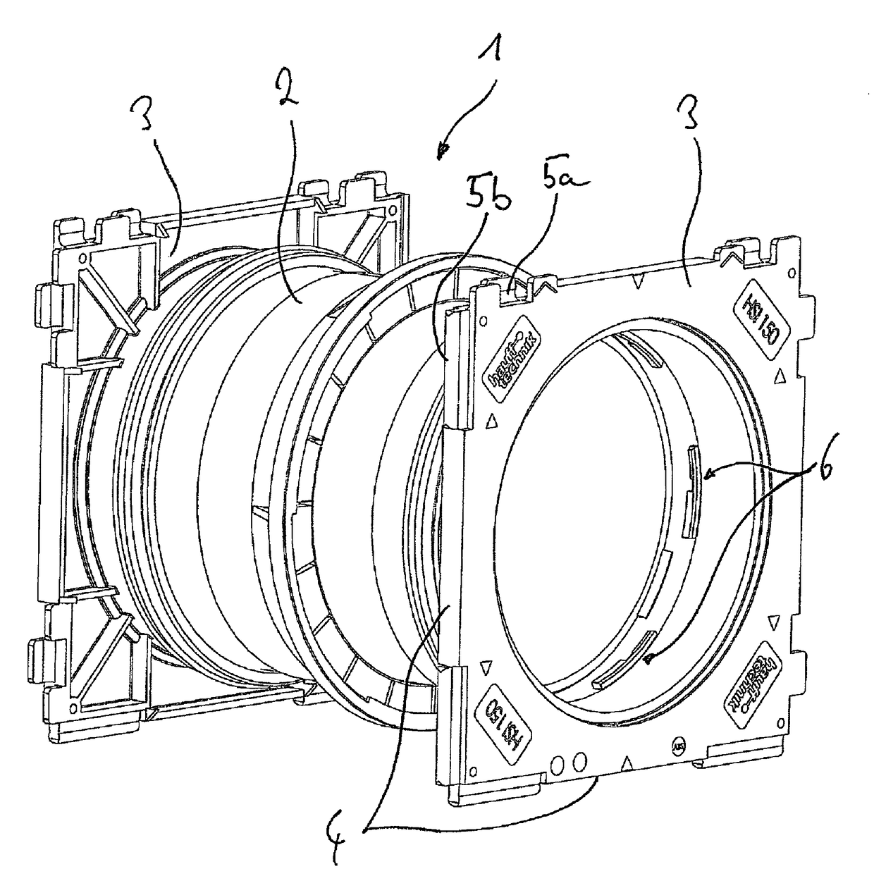
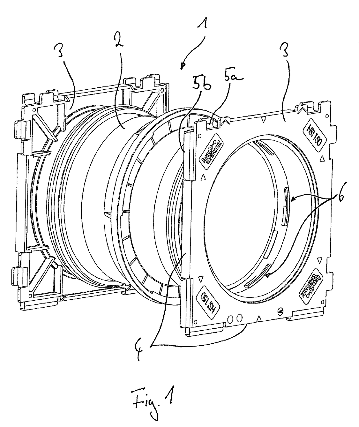
[0063]FIG. 1 shows a duct 1 according to the invention for an insertion into a wall, the duct having a tube element 2. At both ends of the tube element 2, a flange plate 3 is provided respectively as a fixture element. After the insertion of the duct 1 into the wall, the two flange plates 3 lie adjacent to the respective wall area by their outer front face respectively, the tube element 2 keeping clear a through-opening between the two sides of the wall then. Prior to the casting, the duct can be mounted at the formwork by the flange plates 3, for instance by nailing or screwing together with the formwork elements which the flange plates 3 contact with their front faces. Then, the formwork is filled up with concrete and the formwork elements are removed after the latter has hardened.

[0064]At the side edges 4 of the flange plates 3, respectively in an edge region, connection elements are provided, namely groove 5a and tongue elements 5b engaging each other in a form-fit manner. The t...


PUM


Abstract

The invention relates to a feed-through member (1) which is to be mounted in a wall element or floor element and comprises a tube element (2) that includes a first (23) and a second (24) tube element section. Said tube element sections (23, 24) can be moved relative to one another in the conducting direction (21) in such a way that the length of the tube element (2) is adjustable, a blocking mechanism (26, 32; 51, 61) being provided which at least partly prevents the tube element sections (23, 24) from moving when same are in the relative positions.

Description

FIELD OF THE INVENTION[0001]The present invention relates to the use of a duct provided for an insertion into a wall or floor element, having a tube element through which a line can be fed through.BACKGROUND OF THE INVENTION[0002]According to the prior art, for instance in case of so-called manhole liners, tube elements made of fiber cement are provided, which keep clear a through-opening in a wall or floor element after casting in concrete. Therethrough, a line can be fed subsequently and can be sealed against the tube element. Further developments relate to a substitution of the tube elements made of fiber cement by tube elements made of metal or also a synthetic material.[0003]The problem the present invention is to solve is to provide a duct having improved use properties.BRIEF SUMMARY OF THE INVENTION[0004]According to the invention, the problem is solved by a duct for an insertion into a wall or floor element and for feeding through a line, having a tube element which is provi...

Claims


Application Information

Patent Timeline
Patent Type & Authority Patents(United States)
IPC IPC(8): E04G15/00E04G15/06F16L5/02
CPCF16L5/02E04G15/061F16L5/10
Inventor KURZ, RALF
Owner HAUFF TECHN
Why Eureka
Try Eureka