Gas lighting device having simplified fastening means to an electric household appliance, in particular a cooking range

a technology of lighting device and electric household appliance, which is applied in the direction of combustion process, combustion ignition, heating fuel, etc., can solve the problems that the scale economics of electric household appliance manufacturers cannot be obtained, and achieve the effect of reducing size, simple fastening means, and low manufacturing and assembly costs

Active Publication Date: 2018-03-13
ITW IND COMPONENTS SRL
View PDF17 Cites 1 Cited by
  • Summary
  • Abstract
  • Description
  • Claims
  • Application Information

AI Technical Summary

Benefits of technology

[0005]It is thus the object of the present invention to improve the known gas lighting devices by providing a gas lighting device provided with simplified fastening means to the electric household appliance and such that is it possible to mount different gas lighter models on any cooking range model, all of this ensuring low manufacturing and assembly costs, reduced size and high fastening reliability of the gas lighter to the electric household appliance.
[0010]In this manner, it is possible to safely fix a gas lighting device of any model, and thus of any length, onto any cooking range model, exploiting a single perforation, instead of a pair of perforations, thus overcoming the limits of the known art, with great advantage of the manufacturers of electric household appliances. Furthermore, the new gas lighting device according to the invention may also be used on existing cooking ranges, by using only one of the perforations already arranged on the same.

Problems solved by technology

However, because the length of the casing depends on the number of burners which the gas lighting device is adapted to drive, as a result, perforations appropriately arranged at a precise reciprocal distance need to be provided for each gas lighting device model; since any one of the cooking ranges may have a different number of burners, according to the model, the electric household appliance manufacturers do not currently obtain the scale economics which could be achieved if, hypothetically, all the gas lighter models could be mounted on the same pair of perforations.

Method used


Image

  • Gas lighting device having simplified fastening means to an electric household appliance, in particular a cooking range
  • Gas lighting device having simplified fastening means to an electric household appliance, in particular a cooking range

Examples


Embodiment Construction

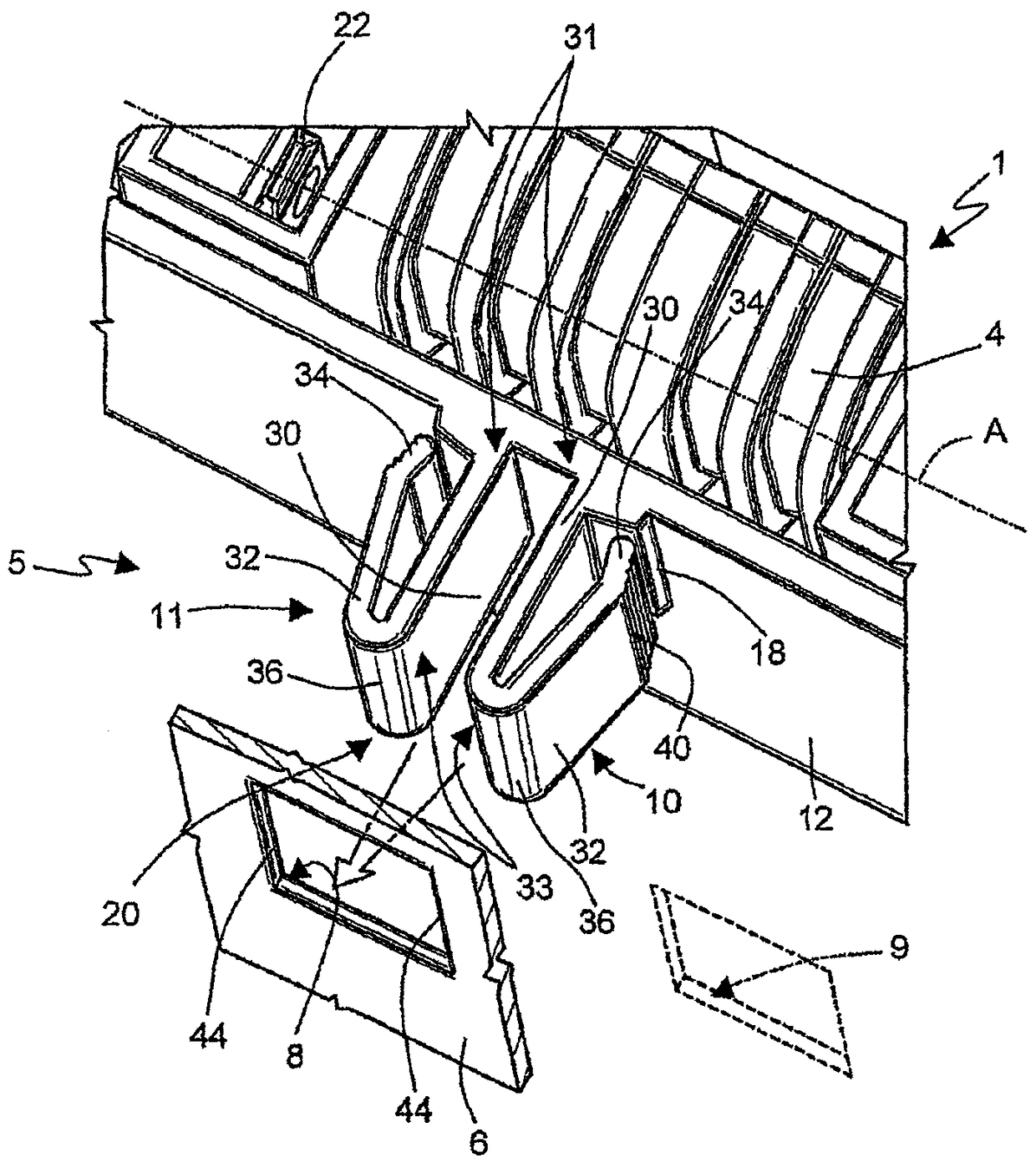
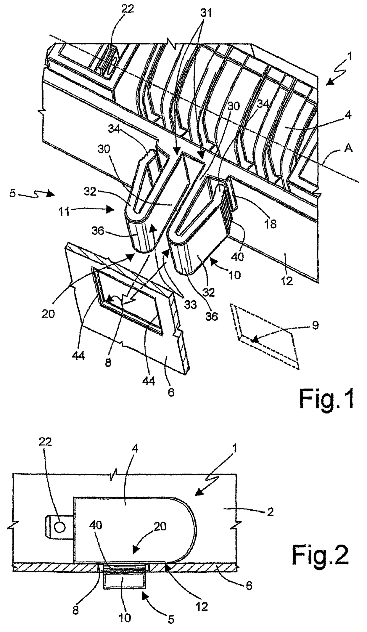
[0014]With reference to FIGS. 1 and 2, numeral 1 indicates as a whole a gas lighting device for an electric household appliance, a cooking range 2 in the non-limiting case in point; the device 1 comprises a casing 4 made of electrically insulating material and fastening means 5 of the casing to a carrying element 6 of the electric household appliance, in the illustrated case in point consisting of an attachment portion for the device 1 of the cooking range 2.

[0015]The fastening means 5 are of the type coupleable with corresponding perforations 8, 9 of the carrying element 6 and consist of at least one pair of elastically deformable fastening elements 10, 11 protrudingly carried by the casing 4. In the illustrated example, the perforations 8,9 are of the traditional type, arranged at a reciprocal predetermined distance through the carrying element 6.

[0016]Unlike the known gas lighting devices, in which the fastening elements intended to couple with the perforations 8, 9 are obtained ...


PUM


Abstract

A gas lighting device having a casing fastenable to an electric household appliance by means of fastening means coupleable with corresponding perforations obtained on a carrying element of the electric household appliance; wherein the fastening means consist of at least one pair of elastically deformable fastening elements protrudingly carried by the casing, perpendicularly to the same, in a position immediately adjacent one to the other so that they are adapted to snappingly couple with only one and the same of said perforations of the carrying element of the electric household appliance.

Description

RELATED APPLICATIONS[0001]The present application is based on International Application Number PCT / IB2008 / 000680 filed Mar. 24, 2008, and claims priority from Italian Application Number TO2007A000218 filed Mar. 26, 2007, the disclosures of which are hereby incorporated by reference herein in their entirety.TECHNICAL FIELD[0002]The present invention relates to a gas lighting device of the type intended to equip an electric household appliance, such as for example a cooking range, provided with simplified fastening means to a carrying element of the electric household appliance.BACKGROUND ART[0003]It is known from EP1101067B1 to the same Applicant an electronic gas lighting device including a casing of electrically insulating material fastenable in use to a carrying element of an electric household appliance, e.g. an attachment portion of a cooking range, by means of at least one pair of perforations arranged at an appropriate reciprocal distance on the carrying element and appropriat...

Claims


Application Information

Patent Timeline
Patent Type & Authority Patents(United States)
IPC IPC(8): G12B9/00F23Q3/00F24C3/10
CPCF23Q3/00F24C3/103
Inventor PIANEZZE, DANIELEALEARDI, MASSIMO
Owner ITW IND COMPONENTS SRL
Why Eureka
Try Eureka