Translucent plastic solar thermal collector

a solar thermal collector and transparent technology, applied in the field of transparent plastic solar thermal collectors, can solve the problems of failure of collectors fabricated from polycarbonate plastics at anywhere near the temperature required for dhw applications, structural defect manifested, and none of the inventions based on high clarity, high strength plastic polycarbonate ever had commercial success, etc., to achieve the effect of reducing manufacturing costs, reducing manufacturing costs, and reducing manufacturing costs

Active Publication Date: 2018-03-13
HELIOS PRODS
View PDF49 Cites 1 Cited by
  • Summary
  • Abstract
  • Description
  • Claims
  • Application Information

AI Technical Summary

Benefits of technology

[0016]Prior to our invention, solar thermal, as provided by the flat-plate collector, has been the most cost effective means of using the sun to provide energy. We have invented a lower cost, more efficient way of producing energy from the sun that can now be utilized to provide more Domestic Hot Water, Space Heating and Space Cooling at a lower cost than has been provided before. Certain features, aspects and advantages of the invention make the system cost-effective enough to be utilized for the high volume Industrial energy products, e.g. Process Heating and Process Cooling, and cost-effective enough for other applications without government subsidies.
[0017]Certain features, aspects and advantages of the present invention directly utilize the sun's rays to heat a liquid. The heat is captured in both the materials of construction of the collector and the fluid contained in the collector. The system overcomes the deficiencies of a flat-plate based system noted above. The collector itself utilizes three dimensions in a one-step process to absorb heat directly from the sun. The collector incorporates durable, lightweight and low-cost materials in its production. The manufacturing process is far less costly than that used to make traditional flat-plate solar collectors. The collector is lighter and easier to install than the cumbersome flat-plate collector, and at long last, the collector results in a plastic product that can be trusted.
[0018]Certain features, aspects and advantages of the present invention utilize the material that is used to build the structure of the collector to directly convert the energy of the sun to heat. The conversion occurs through the use of plastics with low light transmission rather than the broadly sought high light transmission products. At the same time, the fluid contained within the device also converts the sun's energy to heat directly by absorption in addition to conduction from the collector. This combination results in a higher efficiency in the conversion of the energy of the sun to usable heat. The materials of construction cost less and are less energy intensive to produce. There is essentially no fluctuation in terms of price due the idiosyncrasies of the commodities market.
[0027]Certain features, aspects and advantages of the present invention utilize low cost and durable materials that are readily available in the U.S. The materials that may be used in making the product include the broad classes of FRP and thermoplastics. There are further economies from the process used in making our products. As such, the product can be placed in production more rapidly and increases in production can occur seamlessly.

Problems solved by technology

None of the inventions that were patented in the U.S. based on the high clarity, high strength plastic polycarbonate ever had commercial success.
The structural defect manifested itself in failure of collectors fabricated from polycarbonate plastics at anywhere near the temperatures required for DHW applications.
The failure was in the form of pinhole leaks that were difficult to find initially but grew during further use in service.
Upon investigation, the problem appears to have been caused by hydrolysis when water-based or water / glycol based fluids were used within the system.
With oil-based fluids the oil also reduced the operating efficiency of the system.
This rendered the product useless in producing hot water in conventional operating environments.

Method used


Image

  • Translucent plastic solar thermal collector
  • Translucent plastic solar thermal collector
  • Translucent plastic solar thermal collector

Examples


Embodiment Construction

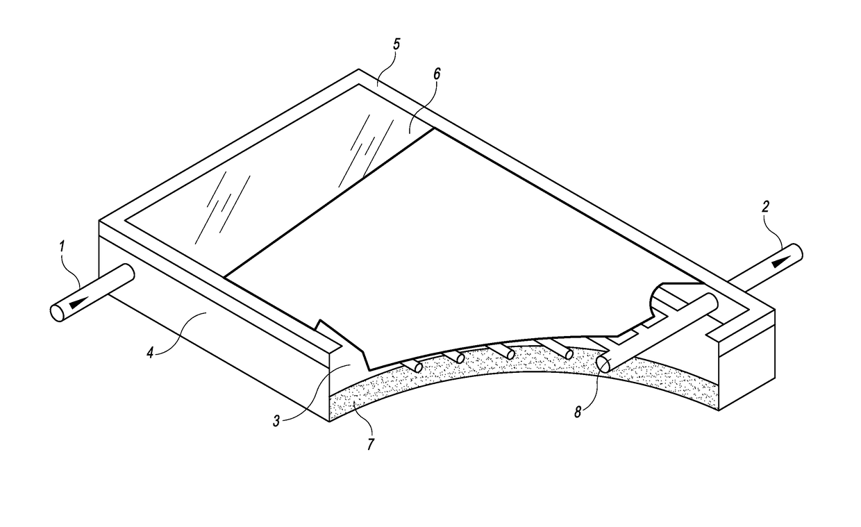
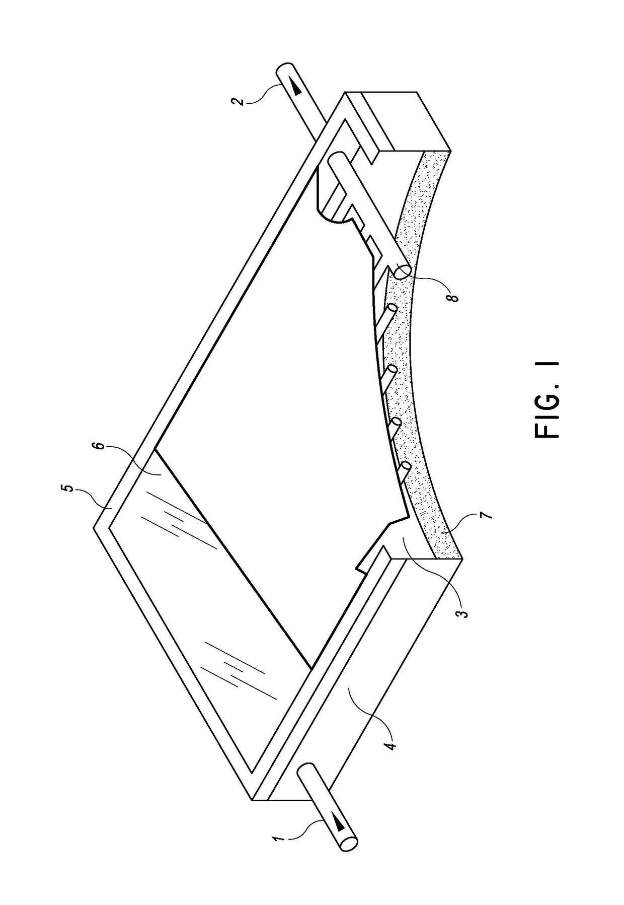
[0040]Certain features, aspects and advantages of the present invention relate to a highly durable, cost-effective version of a solar collector product featuring low-light transmission. In some configurations, the solar collector utilizes a translucent FRP as the material of construction. The solar collector can be based on a high-strength, high-temperature resin that may include about 30% glass content. The collector can feature low-light transmission and can be based on a system that absorbs energy from the sun and converts it to large amounts of heat. The low-light transmission of the material in the collector arises from the color of the resin, the glass loading, and / or the addition of a dye to achieve the final desired effect. Dye can be added when desired in an otherwise moderately clear product or to overcome an otherwise undesired visual effect, e.g., as may be desired in the product when an even higher glass fiber content is used to strengthen the base material.

[0041]Low li...


PUM

PropertyMeasurementUnit
spectrophotometric wavelengthaaaaaaaaaa

Abstract

Our invention consists of two separate and discrete families of polymers, e.g. thermosetting Fiberglass Reinforced Plastics (“FRP”) and thermoplastics. Both are used as the materials of construction to fabricate solar thermal collectors. These families have the same general configuration and are based upon the same principles. Both families are used in a form that some of the walls of the collector are translucent. Both families incorporate a passage through which the thermal fluid flows. Both families make use of dyes to absorb energy from the sun in the fluid and the collector walls. Each of the families makes use of improved collector configurations and designs and special operating approaches. Each family can serve different markets for different solar thermal collectors. In particular, FRP stands alone as an emerging new category of materials for a broad range of applications including everything from novel solar thermal collectors to exotic airplanes.

Description

CROSS-REFERENCE TO RELATED APPLICATIONS[0001]This application is a national stage application under 35 U.S.C. § 371 of International Application No. PCT / US2014 / 021601, filed on Mar. 7, 2014, which published in English as WO 2014 / 164269 A9 on Oct. 9, 2014 and which claims priority benefit of U.S. Provisional Patent Application No. 61 / 779,274, filed Mar. 13, 2013 the entire contents of all of which are hereby incorporated by reference herein.BACKGROUND OF THE INVENTIONField of the Invention[0002]The present invention generally relates to devices used for solar thermal applications or distributed solar thermal applications. In particular, the present invention relates to solar thermal or distributed solar thermal constructions that provide heat and heat-related sources of energy at or near the location where the heat or energy is to be used.Description of the Related Art[0003]Many attempts have been made to develop a replacement for the flat-plate collector. After what some reported in...

Claims


Application Information

Patent Timeline
Patent Type & Authority Patents(United States)
IPC IPC(8): B23P15/26F24D17/00F24S10/40F24S10/50F24S10/55F24S10/70
CPCF24J2/05F24J2/20F24J2/201F24J2/202F24J2/24F24J2/242F24J2/243F24J2/4641F24J2/4643F24J2/506B23P15/26Y02E10/44F24D17/0068F24D2200/04F24D2200/14F24J2002/241F24J2002/4656F24J2002/4692Y02B10/22Y02B10/70F24S80/525F24S10/40F24S10/50F24S10/501F24S10/502F24S10/70F24S10/72F24S10/73F24S80/45F24S80/457F24S2010/71F24S2080/09F24S2080/015Y02B10/20
Inventor LUFTGLASS, MURRAY A.TASCHEK, LOUISGUNHEIM, CLAYTON C.DAHM, KEVIN D.
Owner HELIOS PRODS
Why Eureka
Try Eureka