Methods and apparatus for providing DC power for low voltage lighting

a low-voltage lighting and power supply technology, applied in the field of low-voltage lighting, can solve problems such as the requirement of a standby power level

Active Publication Date: 2018-03-13
THE WATT STOPPER
View PDF11 Cites 2 Cited by
  • Summary
  • Abstract
  • Description
  • Claims
  • Application Information

AI Technical Summary

Benefits of technology

[0004]The devices and methods described below provide for a DC power supply for loads such as lighting. The DC power supply includes low voltage lighting driver electronics along with a supervisory controller that communicates to the driver electronics via any suitable digital communication protocol. The output of each low voltage lighting port includes a third wire that communicates to the low voltage lighting fixture for the purpose of auto-negotiating the appropriate power level without first having to energize the fixture.
[0006]Through the use either of a backplane circuit board or wiring harnesses each driver's output ports include a 3rd wire that communicates to the LED fixture for the purpose of auto-negotiating the appropriate power level without first having to energize the fixture. This allows fixture brands and types to be mixed and even moved from port to port without the risk of damage to the fixture or requiring expertise by the installer to understand how to balance (i.e. bias) LED array power levels for optimal output.
[0014]7. Reduces the number of global controller addresses and / or radios for per-fixture control schemes from 1:fixture to 1:housing-diveristy (likely models are 4 slot, 8 slot, 16 slot, 32 slot) thus reducing commissioning and re-commissioning times;
[0018]11. Added safety through having LED driver assemblies of whatever form factor in a cavity / barrier scheme that isolates high voltage connections from service personnel more effectively than a fixture housing;
[0019]12. Long term serviceability improvement by allowing potentially EOL or expensive drivers to be easily field replaced without fear of damaging the fixture.

Problems solved by technology

Current negotiated power standards lack a requirement for a standby power level to be available such that the load device can turn on active electronics and respond via a full communication stack.

Method used


Image

  • Methods and apparatus for providing DC power for low voltage lighting
  • Methods and apparatus for providing DC power for low voltage lighting
  • Methods and apparatus for providing DC power for low voltage lighting

Examples


Embodiment Construction

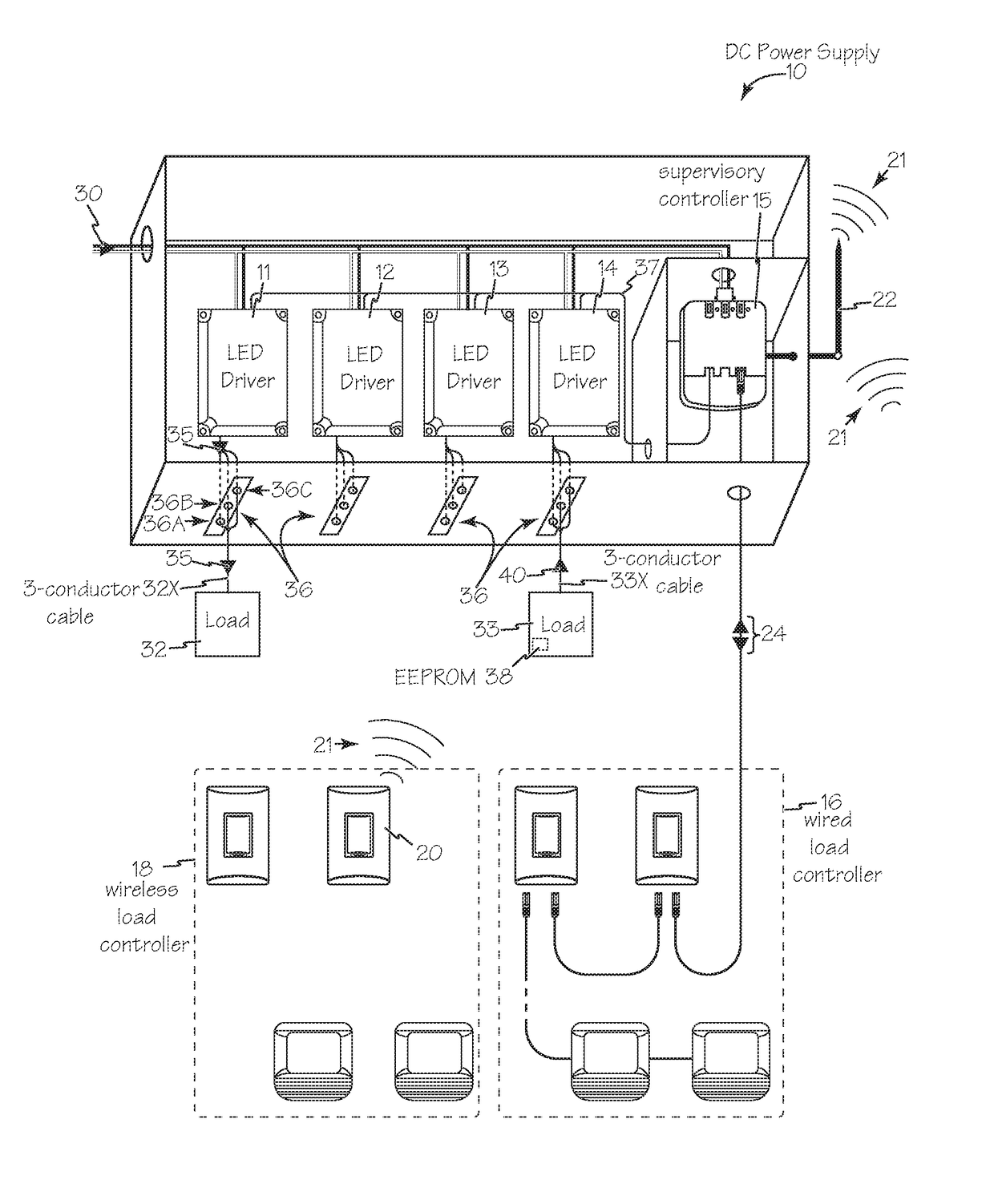
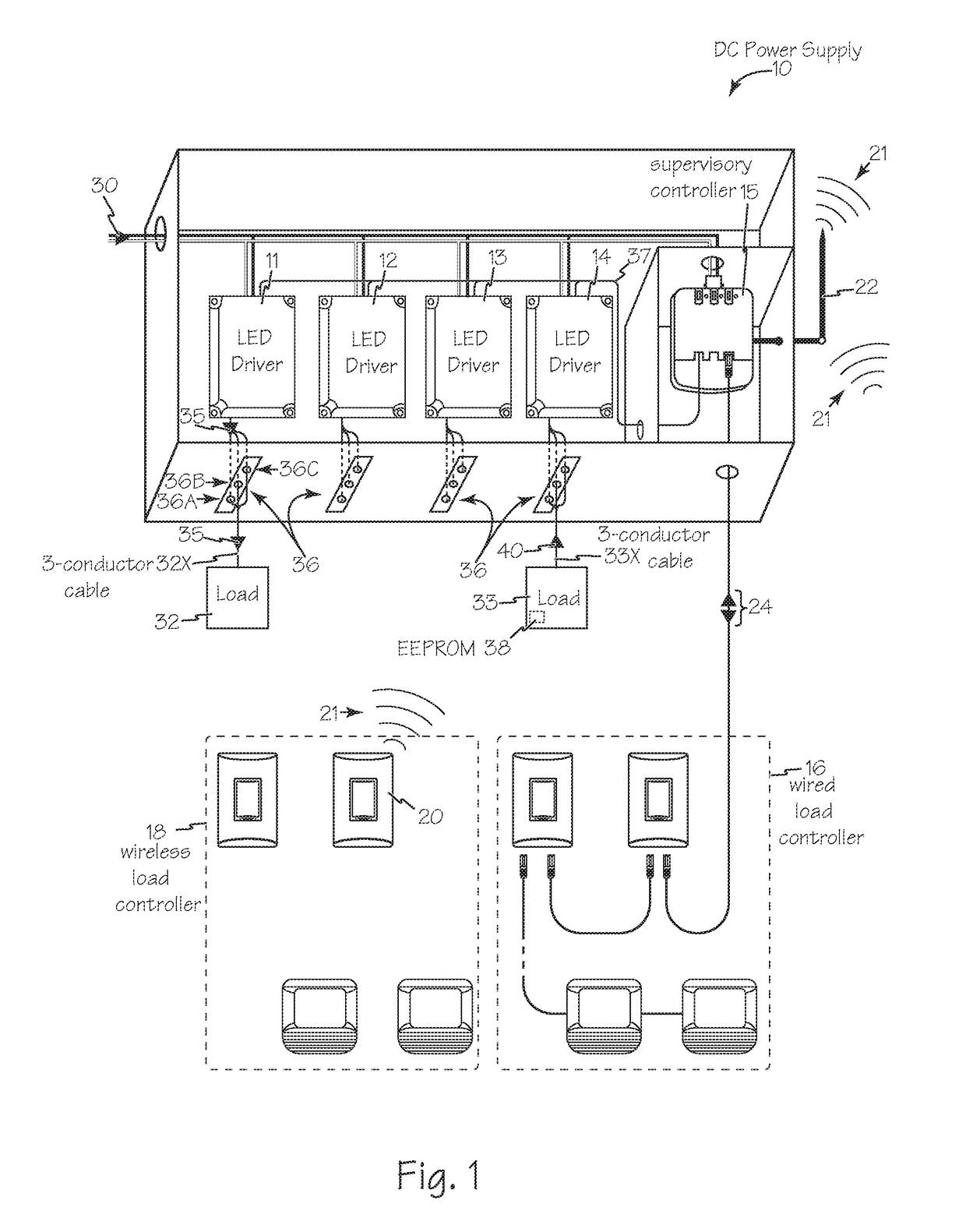
[0023]DC power supply 10 illustrated in FIG. 1 includes one or more LED drivers, such as DC or LED drivers 11, 12, 13 and 14 along with a supervisory controller 15 that communicates with the LED drivers via any suitable method such as digital communications, for example using DALI. Supervisory controller 15 is capable of receiving wired or wireless communication from wired load controllers 16 and wireless load controllers 18 communicating control accessories such as motion detectors, switch stations, ambient light sensors, occupancy sensors and other load controllers. For example wireless load controller 20 exchanges wireless communication signals 21 via antenna 22. Similarly, wired load controllers 16 exchange control signals 24 with supervisory controller 15.

[0024]Any suitable line voltage energy 30 is shared within power supply 10 to provide energy for supervisory controller 15 and LED drivers 11-14. The LED drivers are optimized power supply units for any suitable load such as l...


PUM


Abstract

A DC power supply for lighting includes low voltage driver electronics for any suitable load such as lighting along with a supervisory controller that communicates to the driver electronics via any suitable digital communication protocol. Each driver's output ports include a 3rd wire that communicates to the low voltage load fixture for the purpose of auto-negotiating the appropriate power level without first having to energize the fixture.

Description

[0001]This application claims priority to U.S. Provisional Patent Application 62 / 241,621 filed Oct. 14, 2015.FIELD OF THE INVENTIONS[0002]The inventions described below relate to the field of low voltage lighting.BACKGROUND OF THE INVENTIONS[0003]Current negotiated power standards lack a requirement for a standby power level to be available such that the load device can turn on active electronics and respond via a full communication stack.SUMMARY[0004]The devices and methods described below provide for a DC power supply for loads such as lighting. The DC power supply includes low voltage lighting driver electronics along with a supervisory controller that communicates to the driver electronics via any suitable digital communication protocol. The output of each low voltage lighting port includes a third wire that communicates to the low voltage lighting fixture for the purpose of auto-negotiating the appropriate power level without first having to energize the fixture.[0005]The DC po...

Claims


Application Information

Patent Timeline
Patent Type & Authority Patents(United States)
IPC IPC(8): H05B37/02H02J3/00H02J4/00H02J5/00H02J1/10
CPCH05B37/0272H02J1/10H05B37/0263H02J4/00H02J5/00H02J3/00H05B47/19H05B47/185
Inventor CARTRETTE, JONATHAN P.DAVIS, JEFFREY T.
Owner THE WATT STOPPER
Why Eureka
Try Eureka