Hollow poppet valve

a valve and poppet technology, applied in valve arrangements, machines/engines, mechanical equipment, etc., can solve the problems of unfulfilled heat reduction capability or heat conduction ability of valves, achieve the effect of improving heat reduction capability (heat conduction ability) of valves, enhancing heat transfer, and improving engine performan

Active Publication Date: 2018-03-20
NITTAN VALVE CO LTD
View PDF46 Cites 5 Cited by
  • Summary
  • Abstract
  • Description
  • Claims
  • Application Information

AI Technical Summary

Benefits of technology

[0040]According to the invention, a swirl flow is generated in the valve head cavity during a reciprocal motion of the valve, which helps rotate the coolant in the stem cavity in a circumferential direction, intermixing coolant layers therein, so that the heat reduction capability (heat conduction ability) of the valve is improved due to enhancing the heat transfer by the coolant in the inner cavity, and hence the engine performance also, is improved.
[0041]According to the invention as recited in claim 2, vigorous swirl flows are generated in the valve head cavity during reciprocal motions of the valve, which help rotate the coolant in the stem cavity actively in circumferential directions, stirring the coolant therein, so that the heat reduction capability (heat conduction ability) of the valve is improved due to enhancing the heat transfer by the coolant in the inner cavity, and hence the engine performance also, is further improved.
[0042]According to the invention as recited in claim 3, a smooth swirl flow of coolant along the periphery of the valve head cavity is generated in a lower or an upper region of the valve head cavity, which infallibly stirs the coolant in the valve head cavity and facilitates heat transfer within the internal cavity, hence enhancing the heat reduction capability (heat conduction ability) of the valve. The engine performance is improved accordingly.
[0043]According to the invention as recited in claim 4, since tumble flows are generated in the valve head cavity, along with a swirl flow generated in a reciprocal motion of the valve, the entire coolant is actively stirred in the inner cavity, thereby enhancing the heat transfer by the coolant in the inner cavity, further improving the heat reduction capability (heat conduction ability) of the valve, and hence the engine performance is improved accordingly.

Problems solved by technology

Consequently, thermal energy stored in lower layers of the coolant (near a combustion chamber) is not positively transferred to middle and upper layers of the coolant, so that heat reduction capability (or heat conduction ability) of the valves is not fully achieved.

Method used


Image

  • Hollow poppet valve
  • Hollow poppet valve
  • Hollow poppet valve

Examples


first embodiment

[0055]Referring to FIGS. 1 through 6, there is shown a hollow poppet valve for an internal combustion engine in accordance with the invention.

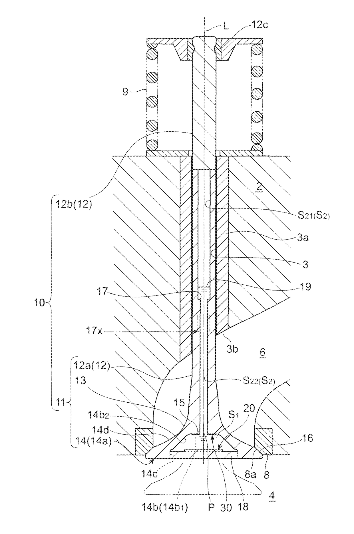
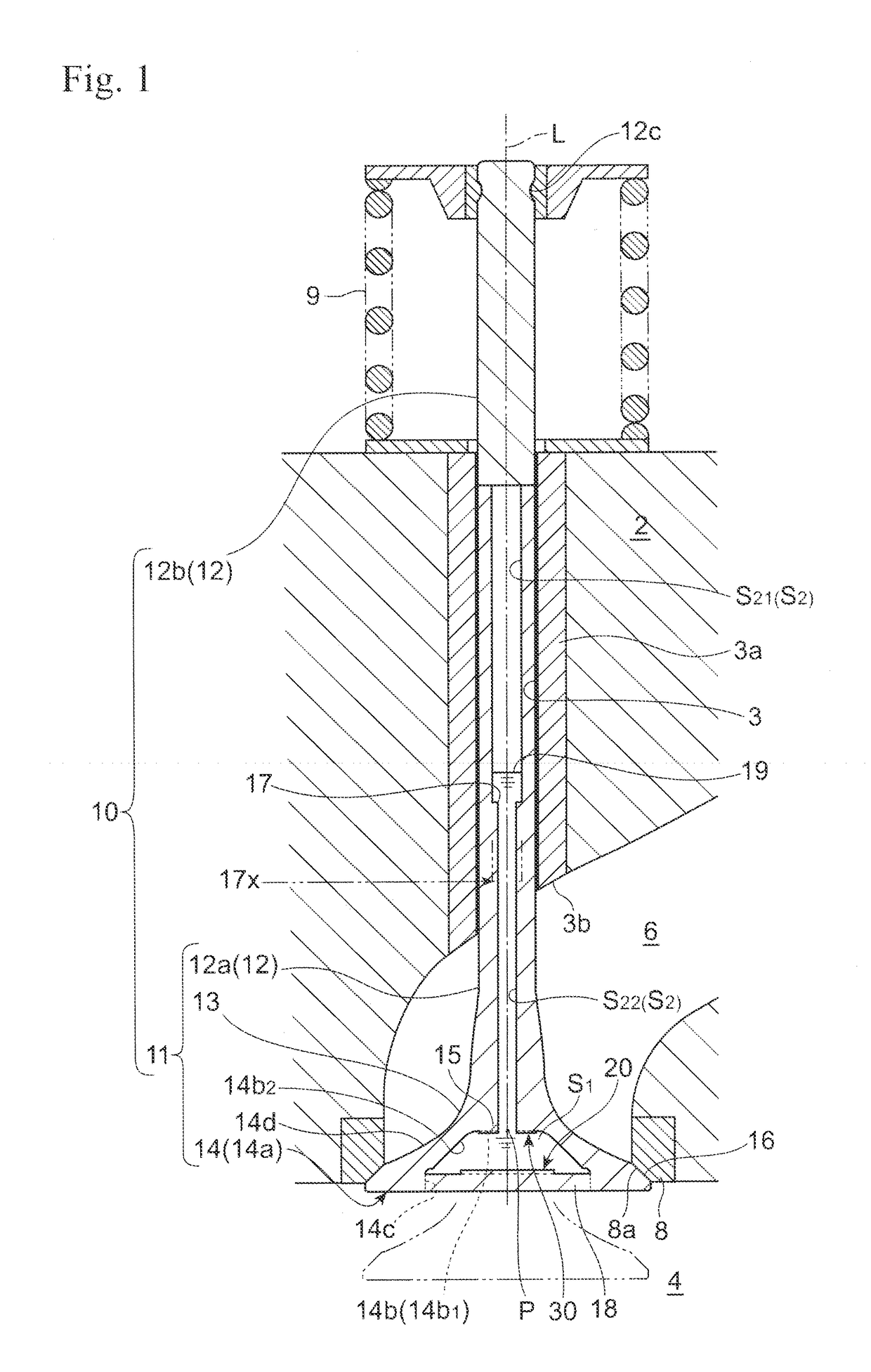
[0056]In these figures, reference numeral 10 indicates a hollow poppet valve made of a heat resisting metal. The valve 10 has a straight stem 12 and a valve head 14 integrated with the stem 12 via a tapered curved fillet 13 that has an outer diameter (that increases towards the valve head). Provided in the peripheral region of the valve head 14 is a tapered valve seat 16.

[0057]Specifically, a hollow poppet valve 10 comprises a valve-head-stem integral shell 11 having a cylindrical stem 12a, a valve head shell 14a formed at one end of the stem 12a, a stem end member 12b welded to another end of the stem 12a, and a disk shape cap 18, as shown in FIGS. 1 and 6. The valve head shell 14a has a generally truncated-circular-cone shape recess 14b, which is sealed with the cap 18 welded onto an inner periphery 14c of the recess 14b. Thus, the hollow po...

third embodiment

[0120]FIGS. 8 and 9 show a hollow poppet valve 10B in accordance with the invention.

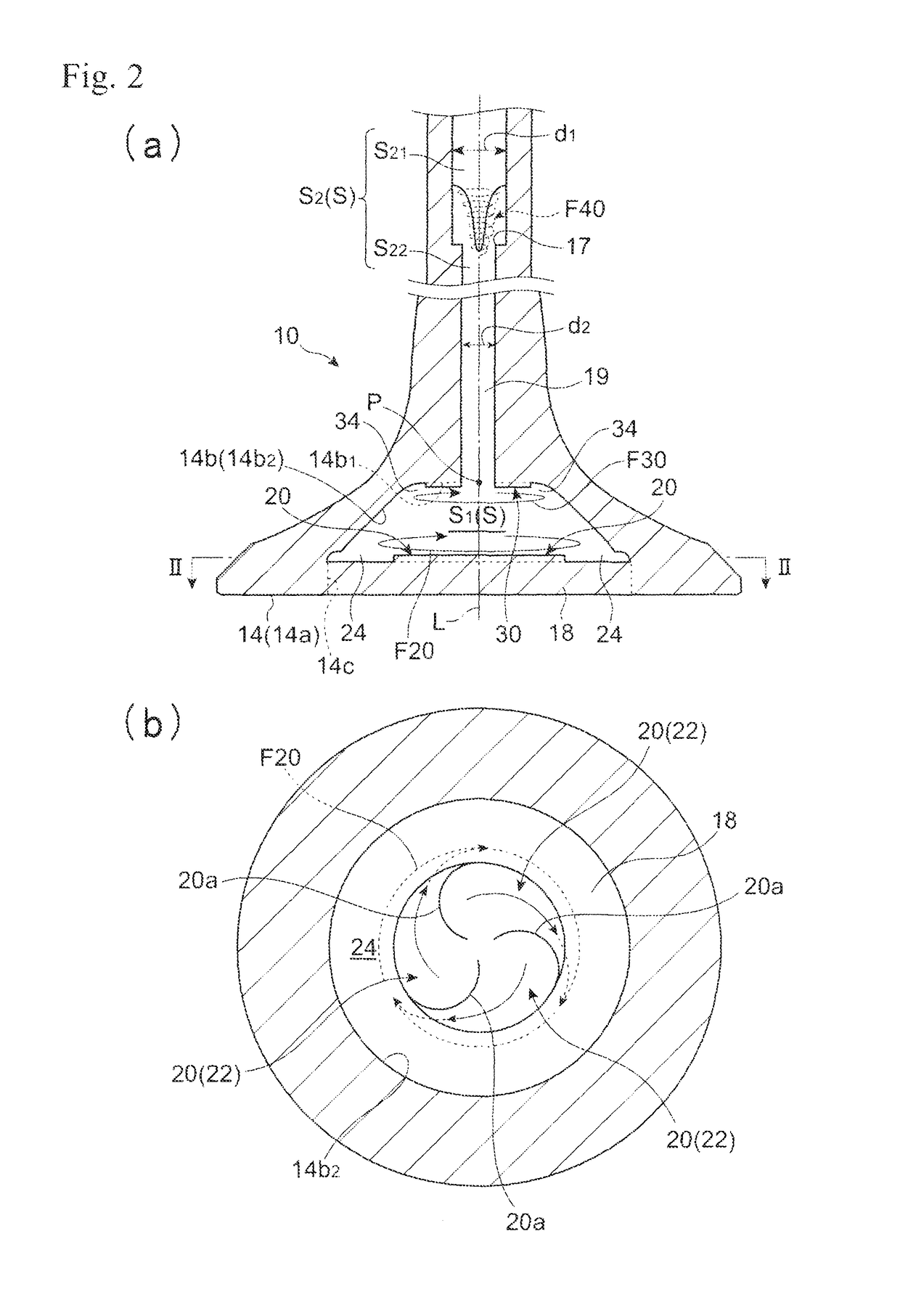
[0121]It is recalled that the stem cavity S2 of the first and second hollow poppet valves 10 and 10A, respectively, has a diametrically larger stem-end side stem cavity S21, a diametrically smaller valve-head side stem cavity S22, and a step 17 in the stem cavity S2. In contrast, the poppet valve 10B has a stem cavity S2′ of a constant inner diameter in the valve stem 12.

[0122]Other structural features of this embodiment are the same as those of the first embodiment, so that like or same elements are simply referred to by the same symbols in these embodiments and further descriptions of the valve 10B will be omitted.

[0123]It should be noted that, unlike in the foregoing poppet valves 10 and 10A in which the coolant 19 is stirred in the stem cavity S2 by the step 17 during a reciprocal motion of the valve, stirring of coolant 19 is not induced in the stem cavity S2 by the step 17 of this poppet valve ...


PUM


Abstract

A hollow poppet valve (10) having an improved heat transfer capability is provided. The valve has an internal cavity (S), extending from within a valve head (14) into a stem (12) of the valve, is loaded with a coolant (19) together with an inert gas. The coolant in the valve head (14) is stirred by swirl flows of the coolant generated during reciprocal motions of the valve. A multiplicity of swirl-forming protrusions are formed on at least on one of the bottom and the ceiling of the valve head cavity (S1) in such a way that swirl flows (F20, F30) of coolant are generated by the protrusions in the valve head cavity (S1) during reciprocal motions of the valve to thereby stir the coolant in the circumferential direction of the cavity (S1).

Description

FIELD OF THE INVENTION[0001]This invention relates to a hollow poppet valve comprising a valve head and a stem integral with the valve head, and more particularly, to a poppet valve having an internal cavity that comprises a diametrically large valve head cavity formed in the valve head and a diametrically small cavity formed in the stem in communication with the valve head cavity, and is charged with a coolant.BACKGROUND ART[0002]Patent Documents 1 and 2 listed below disclose hollow poppet valves comprising a valve head integrally formed at one end of a valve stem, the poppet valve formed with an internal cavity that extends from within a valve head into the stem and is charged, together with an inert gas, with a coolant that has a higher heat conductivity than the valve material. An example of such coolant is metallic sodium having a melting point of about 98° C.[0003]Since this type of internal cavity extends from within the valve head into the stem and contains a large amount of...

Claims


Application Information

Patent Timeline
Patent Type & Authority Patents(United States)
IPC IPC(8): F01L3/14F01L3/20
CPCF01L3/20F01L3/14
Inventor TSUNEISHI, OSAMUICHIMIYA, ATSUYUKI
Owner NITTAN VALVE CO LTD
Why Eureka
Try Eureka