Heating roller, heating device and image forming apparatus

a heating device and heating roller technology, applied in the direction of electrographic process apparatus, instruments, optics, etc., can solve the problems of long warm-up time, slow heating startup process, and excessive deflection of fixing rollers, so as to facilitate the realization of heating devices and uniformly heat the heating rotating member in a short time. , the effect of favorable quality

Active Publication Date: 2008-01-08
SHARP KK
View PDF5 Cites 4 Cited by
  • Summary
  • Abstract
  • Description
  • Claims
  • Application Information

AI Technical Summary

Benefits of technology

[0016]The present invention was created to solve these problems, and it is an object thereof to provide an energy saving heating roller, and a heating device and an image forming apparatus provided with the heating roller, that achieves a reduction in warm-up time by efficiently conducting generated heat to the heating roller surface, as well as that is capable of ensuring favorable releasability even for unfixed images, the releasability of whose color images is difficult to ensure.

Problems solved by technology

However, in halogen lamp-type fixing devices, there has been a problem that the heating startup process is slow, and the warm-up time is long.
However with this, the deflection of the fixing rollers is too great, the pressure in the central part in the longitudinal direction is weak, and there is a limit to how far the thermal capacity can be reduced because of the risk of poor fixing defects.
In particular, with roller-type fixing devices for color image forming apparatuses, there is a thick elastic layer of 1 to 3 mm on the outside portion of the metal core, and so even if the wall thickness of the metal core can be thinned and a reduction in the thermal capacity achieved, the time required for warming-up is still great since the thermal capacity of the elastic layer is large.
Furthermore, poor fixing may occur if the thickness of the elastic layer is reduced, and thus there is a limit to how far the thickness of the elastic layer can be thinned down.
However, in the heating device in the patent Document 1 described above, although it is possible to shorten the warm-up time to less than that when using a conventional halogen lamp, there is a problem in the loss of warm-up time since some of the heat that is generated in the heat generating layer escapes to the inside of the elastic layer.
Furthermore, in accordance with the above noted configuration, when paper containing an unfixed image passes between the rollers, the recording paper winds up onto the heating roller and it is exceedingly difficult to obtain releasability.
In particular, when fixing unfixed color images onto thin paper, it is necessary to fix a maximum of four toner layers on top of each other, and the problem of releasability becomes more acute.
However, since it is necessary to heat the roller from the inside, although originally it has been desirable to only heat the thin-walled tube-shaped body, there is a problem of very poor efficiency because the internal heating roller, which it is not necessary to heat, is heated, and the thin-walled tube-shaped body is indirectly heated using that conducted heat.
However, even if the elastic thermal insulation layer is provided, if the inner surface of the tube-shape member is in close contact with the elastic thermal insulation layer, then the heat is also lost to the inner portion.
Thus, the instant the paper that is carrying the unfixed toner image (recording paper) exits the nip region, the paper winds up on the heating roller without releasing, because of the sagging of the tube-shaped member, and thus paper releasability worsens.
However, if the surface hardness differential between the surface hardness of the heating roller and the elastic roller is 50° or greater, then since the tube-shaped member itself will be too hard, even if the inner elastic thermal insulation layer has low hardness, as for the shape of the nip, the downward facing nip will weaken because the surface hardness of the heating roller will increase, and it becomes difficult to maintain the releasability of the paper.
That is to say, when fixing unfixed color images, it is necessary to fix a maximum of four layered toner layers, and since there are portions that have a layer of toner, and portions that don't, depending on the location, there may be bumps and depressions in the toner surface.
Furthermore, since there may be large bumps and depressions in the paper, depending on the type of paper itself in order to fix the toner following these bumps and depressions, it is necessary to configure the surface of the releasing layer such that it flexibly surrounds the toner.
That is to say, with conventional heating rollers, even if an attempt is made to forcibly separate paper that has a tendency to wind up, it is not possible to catch the paper with a release aiding member that is provided in a proximate position, and thus the paper winds up.
On the other hand, if the inner diameter difference exceeds 2 mm, then it becomes difficult to suppress the meandering of the tube-shaped member.

Method used


Image

  • Heating roller, heating device and image forming apparatus
  • Heating roller, heating device and image forming apparatus
  • Heating roller, heating device and image forming apparatus

Examples


working example 1

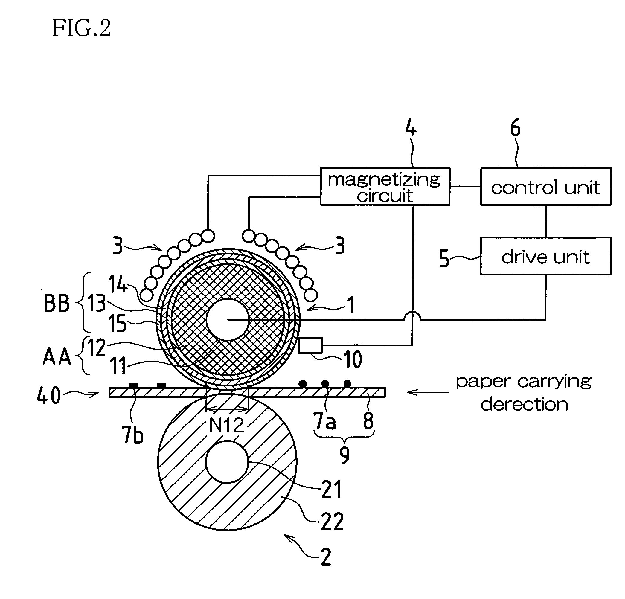
[0098]An experiment was performed to evaluate the releasability of a fixing device having the above-noted configuration, wherein the conditions of the cylindrical member BB were the same, and wherein only the outer diameter of the elastic roller AA was altered from 38.0 to 40.0 mm.

[0099]Evaluation of the releasability was carried out by passing unfixed image samples, which are described next, through the fixing device. Samples that released without problem from the discharge side (that is, released without winding up on the fixing roller (heating roller) 1) were rated “A”, those that discharged with a tendency to wind up on the fixing roller (heating roller) 1, or in which image defects such as toner peeling occurred were rated “B”, those that wound up on the fixing roller (heating roller) 1 were rated “F”, and samples that released without problem but where the image was hot offset (a phenomenon in which a part of the toner from the recording paper remains on the roller after the p...

working example 2

[0114]An experiment was performed to evaluate the releasability of a fixing device having the above-noted configuration, wherein the conditions of the elastic roller AA were the same, and wherein the material of the heat generating layer 13 of the cylindrical member BB was altered from polyimide to nickel (thickness of 40 μm and 30 μm) (however the elastic layer 14 and the release layer 15 were kept the same). The experimental method was the same as in Working Example 1 and is thus omitted.

[0115]When the heat generating layer 13 was nickel with a thickness of 40 μm, the surface hardness t1 of the heating roller 1 was 75° (Asker C), and the hardness differential t3 with the surface hardness (t2=25°) of the elastic roller AA was 50°. On the other hand, the result of a similar measurement when the thickness of the nickel was 30 μm was the surface hardness t1 of the heating roller 1 was 70°, and the hardness differential t3 was 45°. The releasability results taken at this time are shown...

working example 3

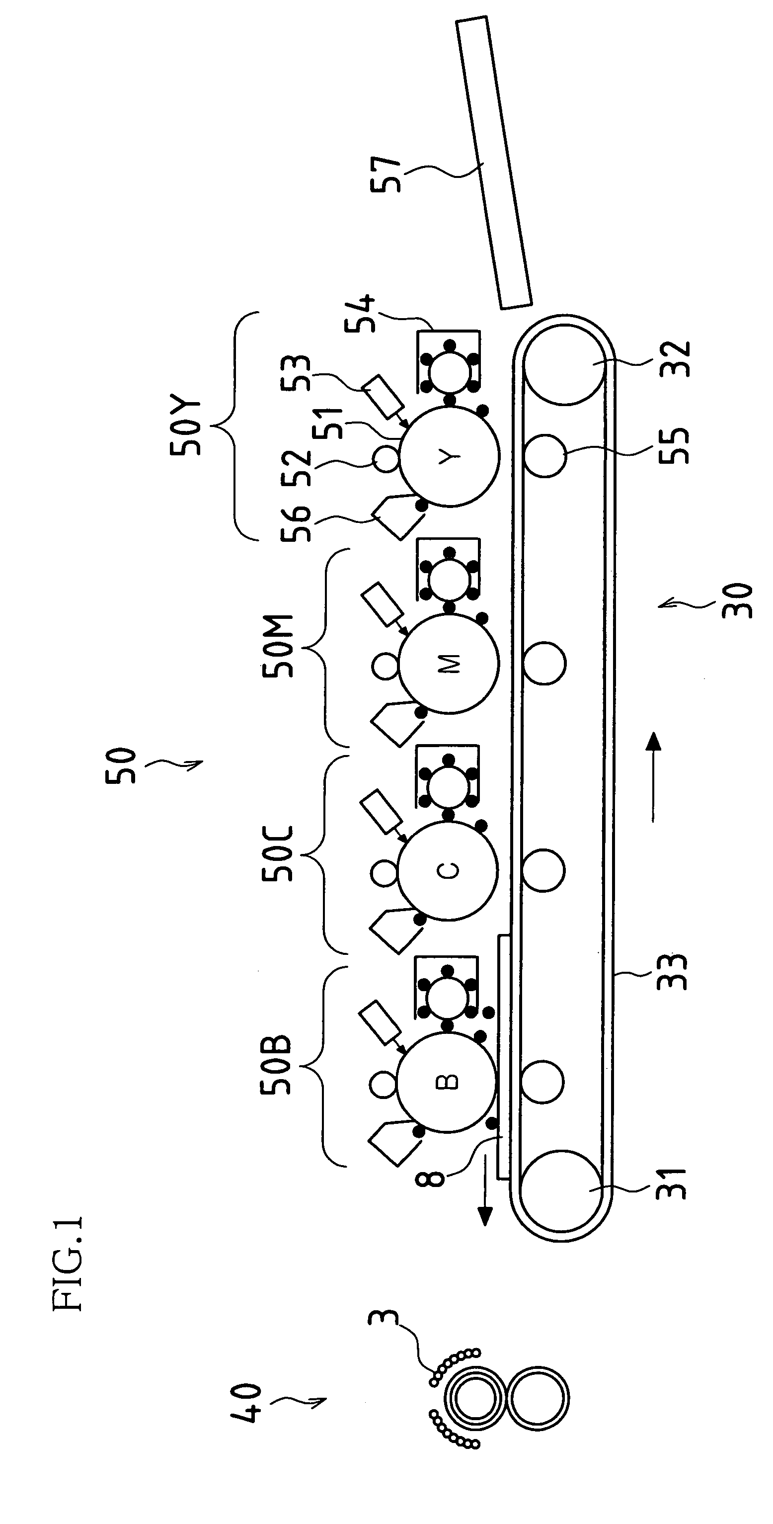
[0120]In the present Working Example 3, an experiment was performed with respect to warm-up time, using the image forming apparatus (an example embodiment) provided with a heating device containing an example embodiment of the heating roller of the present invention (constituted by the cylindrical member and the elastic roller, which are capable of separating, wherein a gap (air layer) is formed between the cylindrical member and the elastic roller), and an image forming apparatus (comparative example) that is provided with a heating device containing a conventional heating roller (in which the cylindrical member and the elastic roller are a single piece that cannot be separated).

[0121]In the experiment, the time (s) taken for the surface of the heating roller to achieve a temperature of 170° C. from room temperature was measured under the following conditions:

[0122]Measured Conditions[0123](1) Power Supply: 1100 W[0124](2) Rotational Speed: 117 mm / s[0125](3) Elastic Roller: Externa...


PUM


Abstract

A heating roller is constituted by an elastic roller AA in which an elastic thermal insulation layer is formed, and an endless cylindrical member BB in which a releasing layer is formed on a thin-film base material (heat generating layer), wherein the elastic roller AA and the cylindrical member BB are constituted such that they are separable, and wherein a slight gap is formed between the elastic roller AA and the cylindrical member BB. Then, when a fixing device is started up and the heating roller is rotated, a deflection B1 of the cylindrical member BB caused by the inner diameter difference between the cylindrical member BB and the elastic roller AA is generated on the paper entry side.

Description

[0001]This application claims benefit of JP 2004-166827, filed 4 Jun. 2004, the entire content of which is hereby incorporated by reference.CROSS REFERENCE TO RELATED APPLICATIONS[0002]This application claims priority under 35 U.S.C. § 119(a) on Patent Application No. 2004-166827 filed in Japan on Jun. 4, 2004, the entire contents of which are hereby incorporated by reference.BACKGROUND[0003]1. Technical Field[0004]The present invention relates to heating rollers and heating devices that are provided with the rollers, and to image forming apparatuses, and particularly relates to energy saving heating rollers, heating devices and imaging apparatuses that can warm up in a short time, and that can uniformly heat a material that is to be heated.[0005]2. Description of the Related Art[0006]Halogen lamp type fixing devices, which are one type of heating device, and which are constituted by arranging a halogen lamp within a fixing roller made of a hollow metal core of, for example, aluminu...

Claims


Application Information

Patent Timeline
Patent Type & Authority Patents(United States)
IPC IPC(8): G03G15/20
CPCG03G15/2053G03G2215/2051
Inventor MAEDA, TOMOHIRO
Owner SHARP KK
Why Eureka
Try Eureka