
Flexible electric heating pad

a flexible electric heating pad and heating element technology, applied in the direction of ohmic-resistance heating, heating element shapes, electrical apparatus, etc., can solve the problems of limiting the application of the product, excessive abradement of the heating element after long-term use, easy oxidation of the printed circuit, etc., to prevent the risk of electric shock, enhance the strength of the flexible electric heating pad, and prevent the effect of oxidation of the printed layer

Inactive Publication Date: 2006-06-01
LIANG CHIN SHEN
View PDF2 Cites 4 Cited by
  • Summary
  • Abstract
  • Description
  • Claims
  • Application Information

AI Technical Summary

Benefits of technology

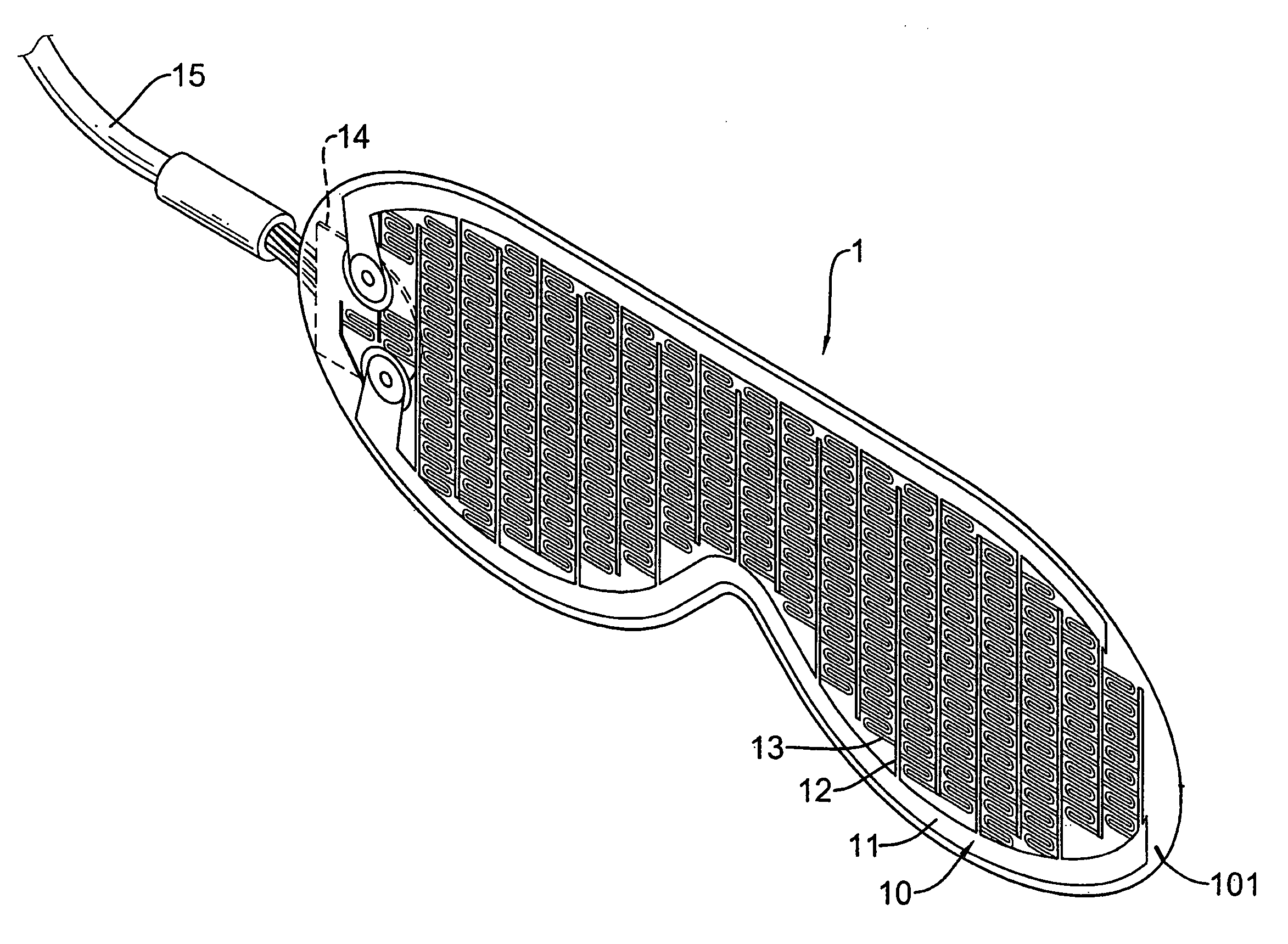
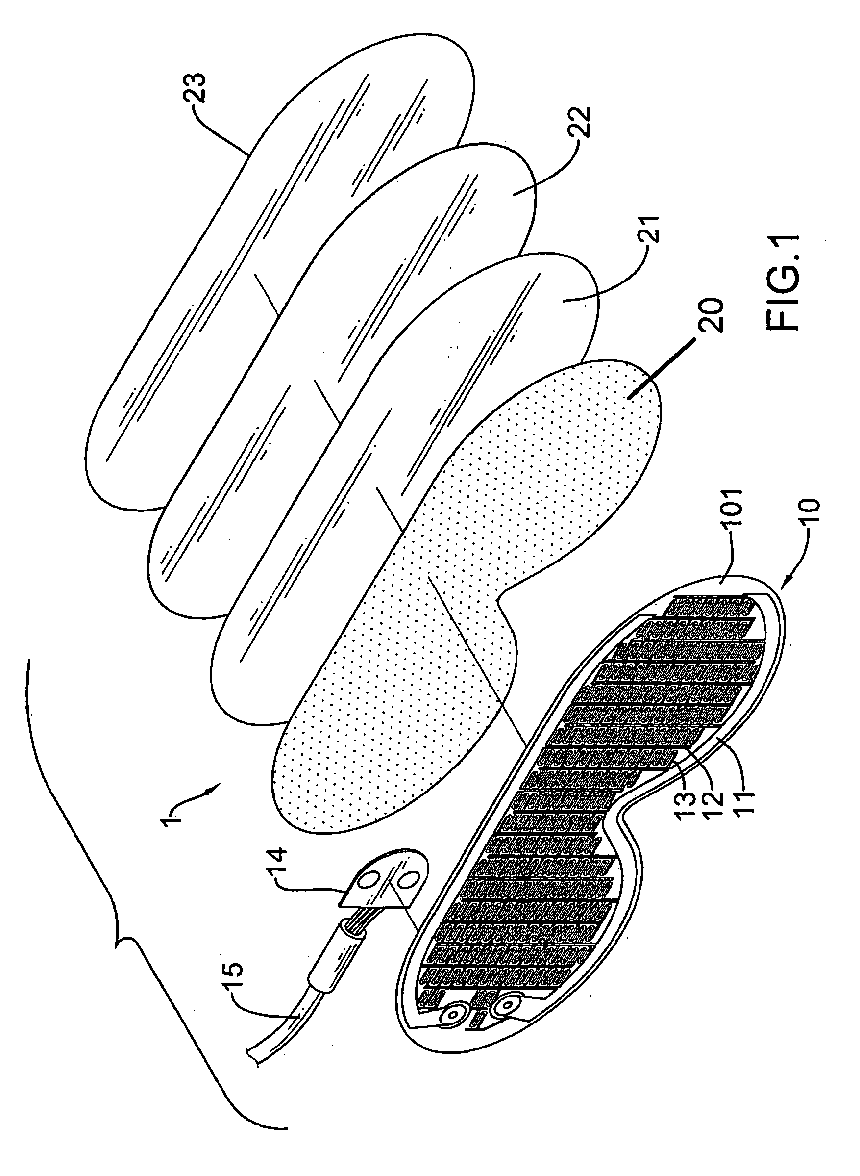
[0012] A flexible electric heating pad in accordance with the present invention includes a first layer 10, a glue 20, a first laminate layer 21, an aluminum foil sheet, and a second laminate layer. The first layer 10 comprises a conducting wires 12, electrical resistances 13, and a circuit board 14. In view of the above-mentioned conventional drawbacks, a flexible electric heating pad of the present invention is provided, which can enhance a strength of the flexible electric heating pad, distribute heat conduction evenly, prevent oxidization, avoid electrocution of users, and endure abrasion.
[0014] With a design of the flexible electric heating pad of the present invention, the strength of the flexible electric heating pad is enhanced. In addition, the aluminum foil sheet generates an even heat conduction effect. The additional laminate layers of a first laminate layer and a second laminate layer having the aluminum foil sheet sandwiched in-between can be adhered to the external exposed side of the surface of the printed layer, which can prevent oxidation of the printed layer. The external exposed side of the surface of the printed layer also can be hermetically sealed to prevent the risk of electric shock due to the conducting wires of the printed layer becoming exposed, and also the printed layer includes a good effect to endure abrasion. Thereby the flexible electric heating pad is more suitable than the conventional flexible electric heating element to be manufactured into all kinds of shapes and covered with a layer of cotton for use.

Problems solved by technology

However, this conventional flexible heating pad has the following drawbacks:
The printed circuit is formed on only one side of the plastic material, thereby limiting application of the product.
The printed circuit oxidizes easily due to lack of protection.
The heating element abrades excessively after long-term use.
The conductive wires break too easily The laminate layer distorts in shape due to excessively high temperatures.

Method used


Image

  • Flexible electric heating pad
  • Flexible electric heating pad
  • Flexible electric heating pad

Examples


Embodiment Construction

[0020] The flexible electric heating pad of the present invention mainly includes an aluminum foil sheet sandwiched between a first laminate layer and a second laminate layer of a flexible material on an external exposed side of a surface of the printed layer, so as to enhance a strength of the flexible electric heating pad, to conduct heat evenly and prevent oxidation, and further to prevent electric shock and resist abrasion.

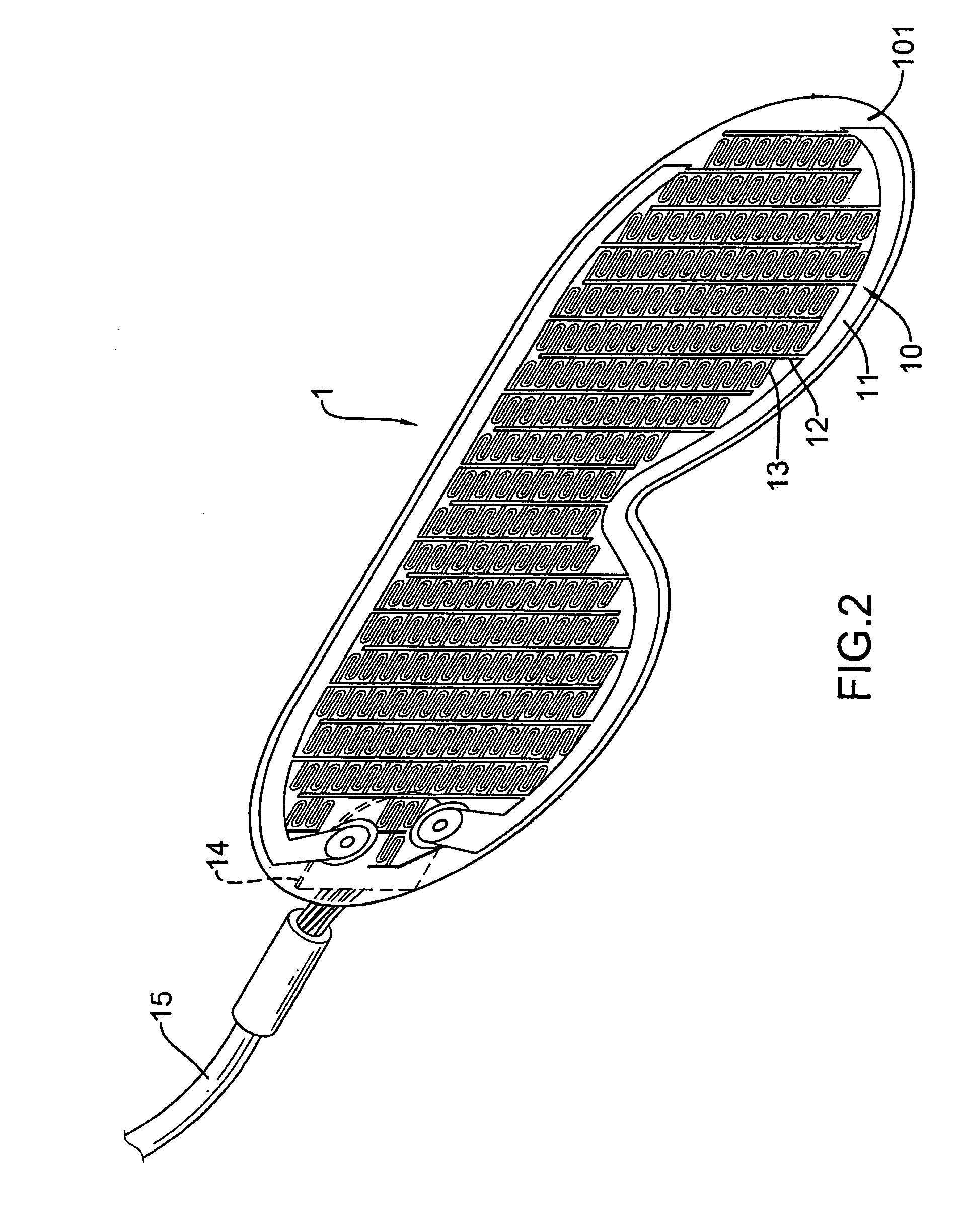
[0021] Referring to FIG. 1, FIG. 2 and FIG. 3, a flexible electric heating pad 1 of the present invention pad includes a printed layer 11 on a lateral surface of a first laminate layer 101. The printed layer 11 includes a plurality of distributed conducting wires 12 and a plurality of connected electric resistances 13. A circuit board 14 is set at a contact point of positive and negative conducting wires 12 of a lateral end of the printed layer 11. An electric wire 15 connected to the circuit board 14 can be plugged into a power supply terminal.

[0022] A feat...


PUM


Abstract

A flexible electric heating pad has a first laminate layer, a second laminate layer, and a printed layer formed on the first laminate layer. The printed layer includes a plurality of distributed conducting wires and a plurality of connected electric resistances. A circuit board is set at a contact point of positive and negative conducting wires of the printed layer. An electric wire connected to the circuit board can be plugged in a power supply terminal. An aluminum foil sheet is sandwiched between the laminate layers on an external exposed side of a surface of the printed layer.

Description

BACKGROUND OF THE INVENTION [0001] 1. Field of the Invention [0002] The invention relates in general to a flexible electric heating pad, and more particularly to a flexible electric heating pad design that can enhance strength of the flexible electric heating pad, achieve a uniform heat conduction, prevent both oxidation and electric shock, and can resist abrasion. [0003] 2. Description of the Related Art [0004] Flexible electric heating elements are conventionally used as components of electrothermal equipment. Referring to FIG. 4 and FIG. 5, a flexible electric heating element 3 has a printed layer 31 formed on a lateral surface of a laminate layer 30. The printed layer 31 includes a plurality of conducting wires 32 and a plurality of electric resistances 33. A circuit board 34 is set at a contact point of positive and negative conducting wires 32 of a lateral end of the printed layer 31. An electric wire 35 connected to the circuit board 34 can be plugged in a power supply termin...

Claims


Application Information

Patent Timeline
IPC IPC(8): H05B3/34
CPCH05B3/36H05B2203/005H05B2203/016H05B2203/017
Inventor LIANG, CHIN-SHEN
Owner LIANG CHIN SHEN
Learn More