Light-emitting display panel

a technology of light-emitting display panel and display panel, which is applied in the direction of lighting support devices, identification means, instruments, etc., can solve the problems of large amount of heat generated, reduced light-emitting efficiency of light-emitting diodes, and large emitter chips, so as to increase heat dissipation efficiency, large surface area, and the effect of increasing the heat dissipation efficiency

Inactive Publication Date: 2011-08-16
ENRAYTEK OPTOELECTRONICS
View PDF12 Cites 5 Cited by
  • Summary
  • Abstract
  • Description
  • Claims
  • Application Information

AI Technical Summary

Benefits of technology

[0011]The light-emitting display panel, according to the invention, therein includes a light engine which effectively integrates the N heat-conducting / dissipating apparatuses with the N light-emitting apparatuses into an independent light engine having a heat-dissipating function. The heat generated by the N light-emitting apparatuses can be effectively conducted by the cylindrical heat-conducting device. The heat-conducting device not only has a larger surface area compared to that of the prior art, but can also conduct the heat away from the N light-emitting apparatuses and can dissipate the heat into the surrounding air by the at least one heat-dissipating fin to substantially increase the heat-dissipating efficiency. Compared with prior art, because the N light-emitting apparatuses are flatly mounted on the flat portion of the heat-conducting device, the N light-emitting apparatuses of the light-emitting display panel, according to the invention, can effectively lower the junction temperature, allowing the light-emitting display panel to be able to utilize the high-power light-emitting diodes to display words and graphic files and to serve as a planar lighting source.
[0012]The light-emitting display panel, according to the invention, can integrate the light-emitting apparatuses with the heat-conducting / dissipating apparatuses into an independent member that can effectively dissipate heat and has a better heat-dissipating efficiency.

Problems solved by technology

However, if the light-emitting intensity of a light-emitting diode needs to be increased, a bigger emitter chip is required, and a larger amount of heat is also generated.
After continuous light emission of the light-emitting diode for a period of time, the light-emitting diode will have the problem of an increased junction temperature, causing the light-emitting efficiency of the light-emitting diode to drop, which in turn makes the brightness of the light-emitting diode not able to increase.

Method used


Image

  • Light-emitting display panel
  • Light-emitting display panel
  • Light-emitting display panel

Examples


Embodiment Construction

[0016]The present invention provides a light-emitting display panel made up of N high-power light-emitting apparatuses, and the light-emitting display panel can prevent the light-emitting efficiency and product life of the emitter chip to decrease when the temperature at the P-N junction becomes exceedingly high.

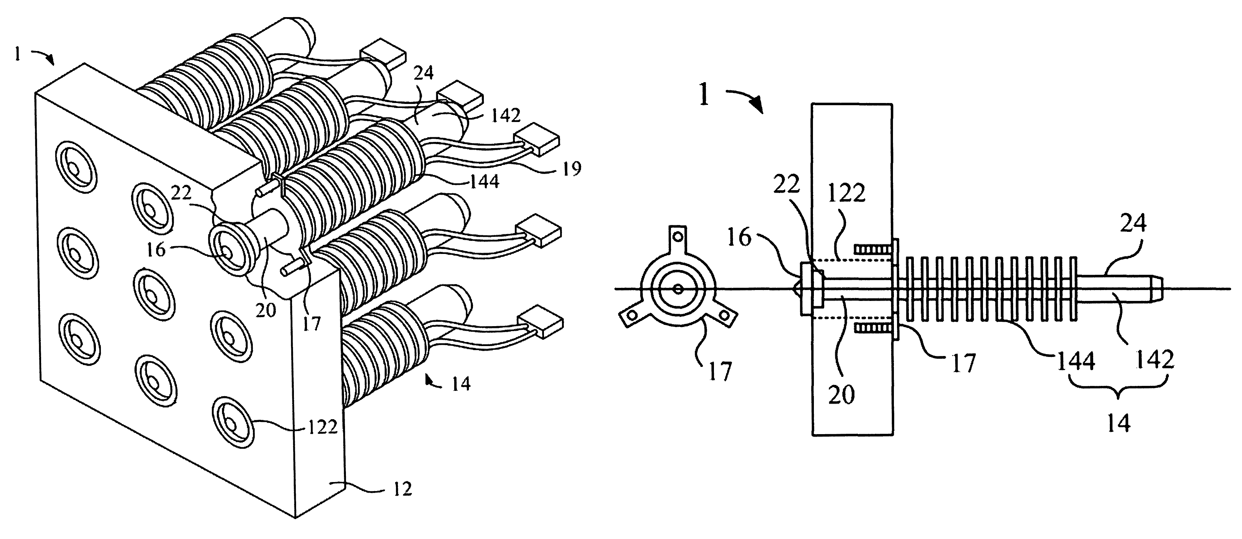
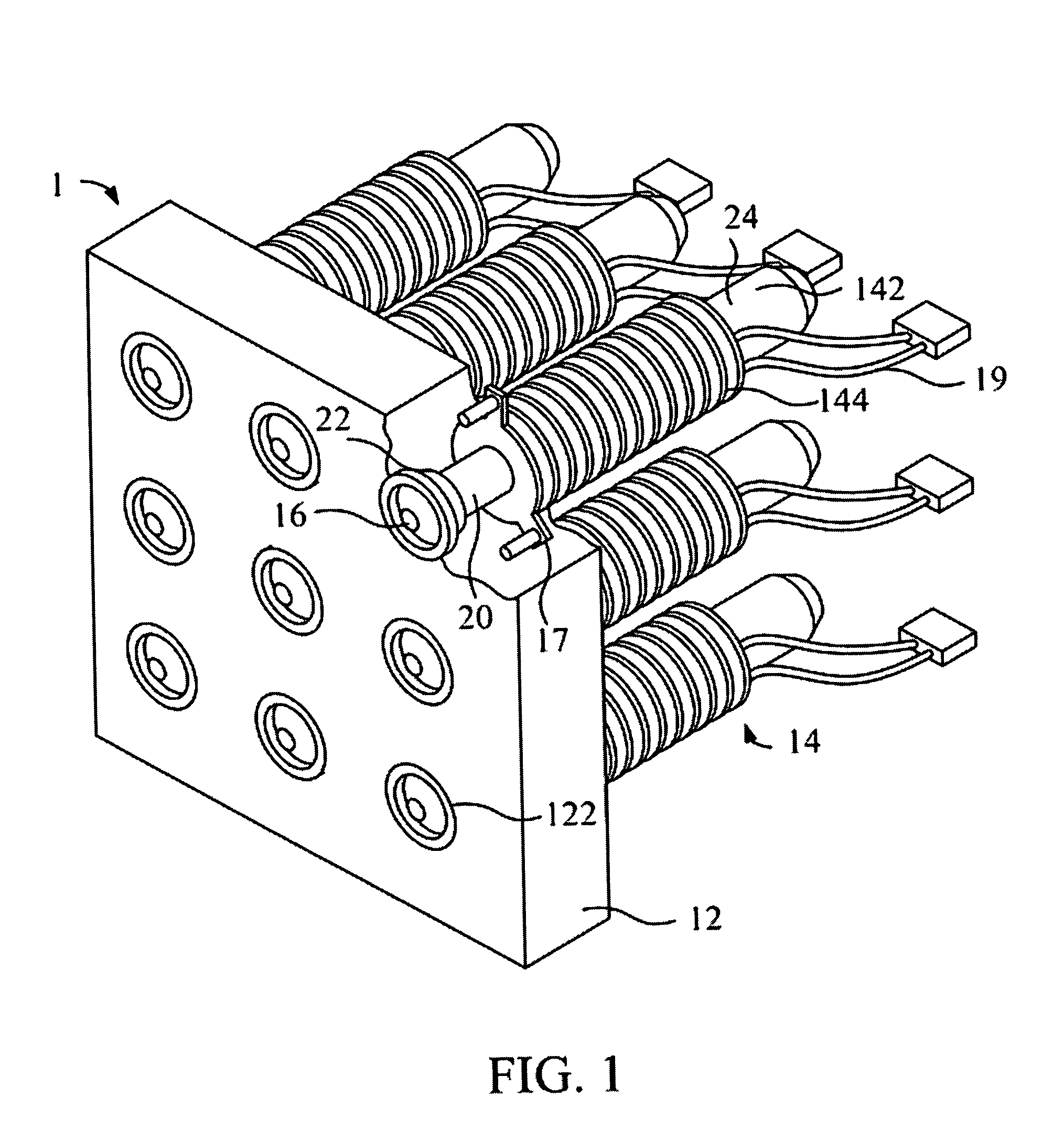
[0017]Referring to FIG. 1, FIG. 1 is an outside perspective view of a first preferred embodiment according to the invention. As shown in FIG. 1, the light-emitting display panel 1 includes a front plate 12, N heat-conducting / dissipating apparatuses 14, and N light-emitting apparatuses 16. N is a natural number.

[0018]The front plate 12 thereon defines a front side and a back side, and the front plate 12 has thereon N formed-through apertures 122. The inner diameter of each of the N apertures 122 is slightly greater than the external diameter of the light-emitting apparatus 16 corresponding to the aperture 122. The front plate 12 is made from one selected from the group consis...


PUM


Abstract

The invention relates to a light-emitting display including a front plate, N heat-conducting / dissipating apparatuses, and N light-emitting apparatuses, wherein N is a natural number. The front plate has N formed-through apertures thereon. Each of the N heat-conducting / dissipating apparatuses, corresponding to one of the N formed-through apertures and one of the N light-emitting apparatuses, is inserted into the corresponding aperture via a neck portion thereof. Each of the N light-emitting apparatuses is mounted on the flat portion of the corresponding heat-conducting / dissipating apparatus. Thereby, the heat generated during the operation of each of the N light-emitting apparatuses is conducted by the corresponding heat-conducting / dissipating apparatus to the back side of the front plate, and then it is dissipated by the corresponding heat-conducting / dissipating apparatus.

Description

BACKGROUND OF THE INVENTION[0001]1. Field of the Invention[0002]The present invention relates to a light-emitting display panel; in particular, respective light-emitting apparatuses of the light-emitting display panel according to the invention are engaged to highly efficient heat-conducting / dissipating apparatuses, so that the respective light-emitting apparatuses can operate under high power to increase the light-emitting intensity of each of the respective light-emitting apparatuses.[0003]2. Description of the Prior Art[0004]Light-emitting diodes are a kind of emerging lighting source which has many advantages, such as power-saving, shake-resistant, rapidly-responding, and applicable to mass production. Many of the current light-emitting display panels adapt the light-emitting diodes as a light-emitting source of light-emitting apparatuses, and these light-emitting display panels are widely applied in many situations, such as traffic signals, advertising boards, scoreboards in fi...

Claims


Application Information

Patent Timeline
Patent Type & Authority Patents(United States)
IPC IPC(8): F21V29/00H01L33/64
CPCG09F9/33H05K7/20963F21Y2101/02F21V29/006F21Y2115/10F21V29/51F21V29/717F21V29/74
Inventor CHEN, JEN-SHYAN
Owner ENRAYTEK OPTOELECTRONICS
Why Eureka
Try Eureka