Eureka AIR delivers breakthrough ideas for toughest innovation challenges, trusted by R&D personnel around the world.

Spacer for Insulating Glass Panes

a technology of insulating glass and spacers, which is applied in the direction of doors/windows, building components, construction, etc., can solve the problems of reducing the overall limited desiccant capacity, etc., and achieves the effect of reducing weight, heat conduction, and total heat transfer resistance of the spacer in accordan

Active Publication Date: 2018-10-18
ROLLTECH
View PDF10 Cites 5 Cited by
  • Summary
  • Abstract
  • Description
  • Claims
  • Application Information

AI Technical Summary

Benefits of technology

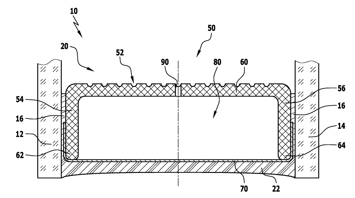
The invention is related to a spacer used in the manufacturing of glass panels. The spacer has a cavity between its inner wall and a vapor diffusion barrier, which is made of a poorly heat-conducting material, reducing heat conduction between the glass panes and increasing the overall heat transfer resistance of the spacer. Additionally, the invention includes the use of ultrathin glass tape which is shaped to match the contour of the profile body, and which is elastically deformed to avoid shear forces and facilitate connection to the profile body. These features improve the manufacturing process and the overall quality of the glass panels.

Problems solved by technology

The capacity of the desiccant is limited, however, such that the interspace between the panes being closed off also by the spacer in a gastight, in particular moisture-tight, manner is of vital importance.
Full-metal films made, i.e., of aluminum or steel have a pronouncedly good heat conductivity of about 200 and 50 W / (K·m), respectively, and thereby reduce the heat transfer resistance of the spacer overall.

Method used


Image

  • Spacer for Insulating Glass Panes
  • Spacer for Insulating Glass Panes
  • Spacer for Insulating Glass Panes

Examples


first embodiment

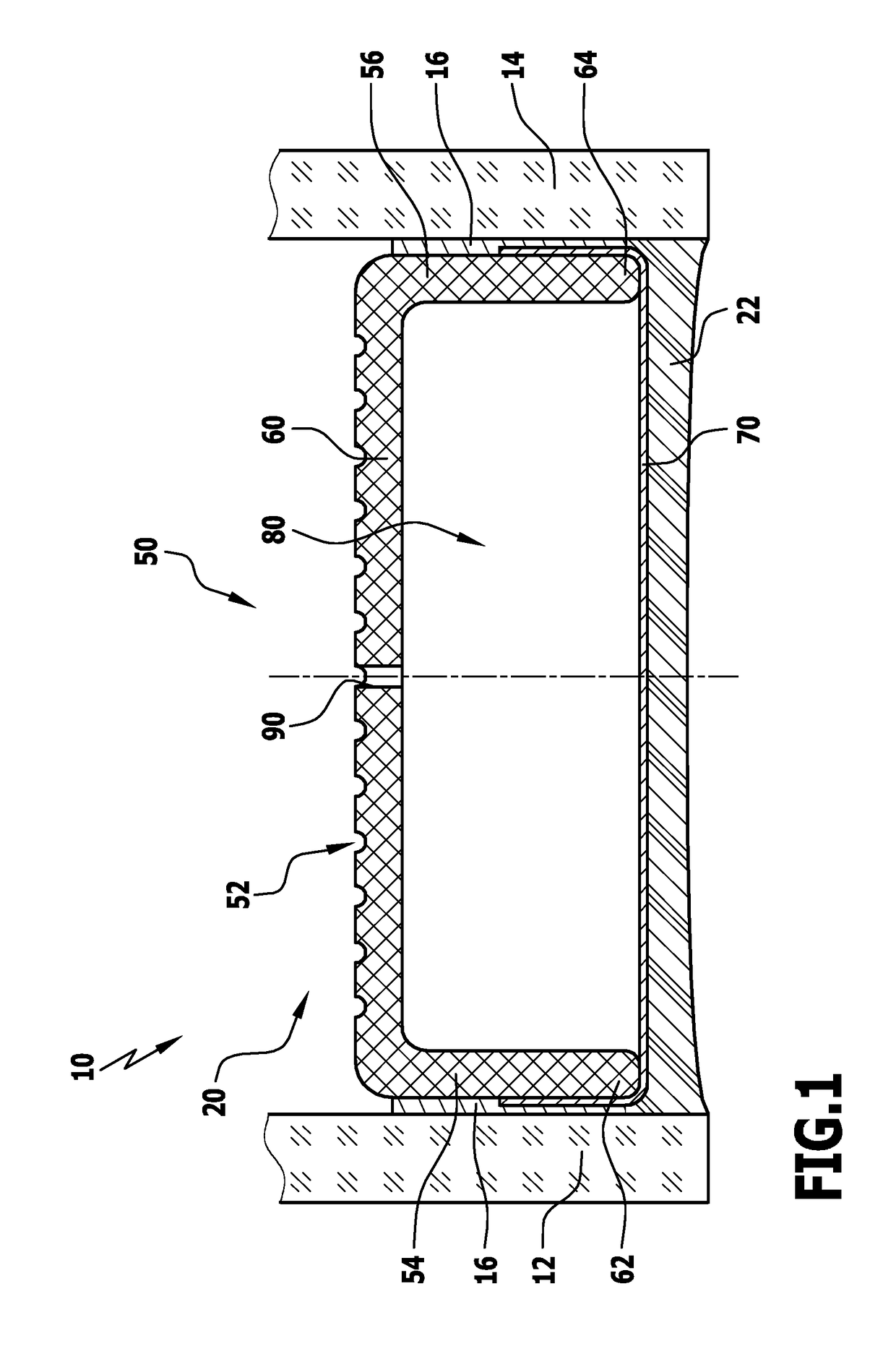
[0142]FIG. 1: a spacer in accordance with the invention in its installation situation in an insulating glass pane;

second embodiment

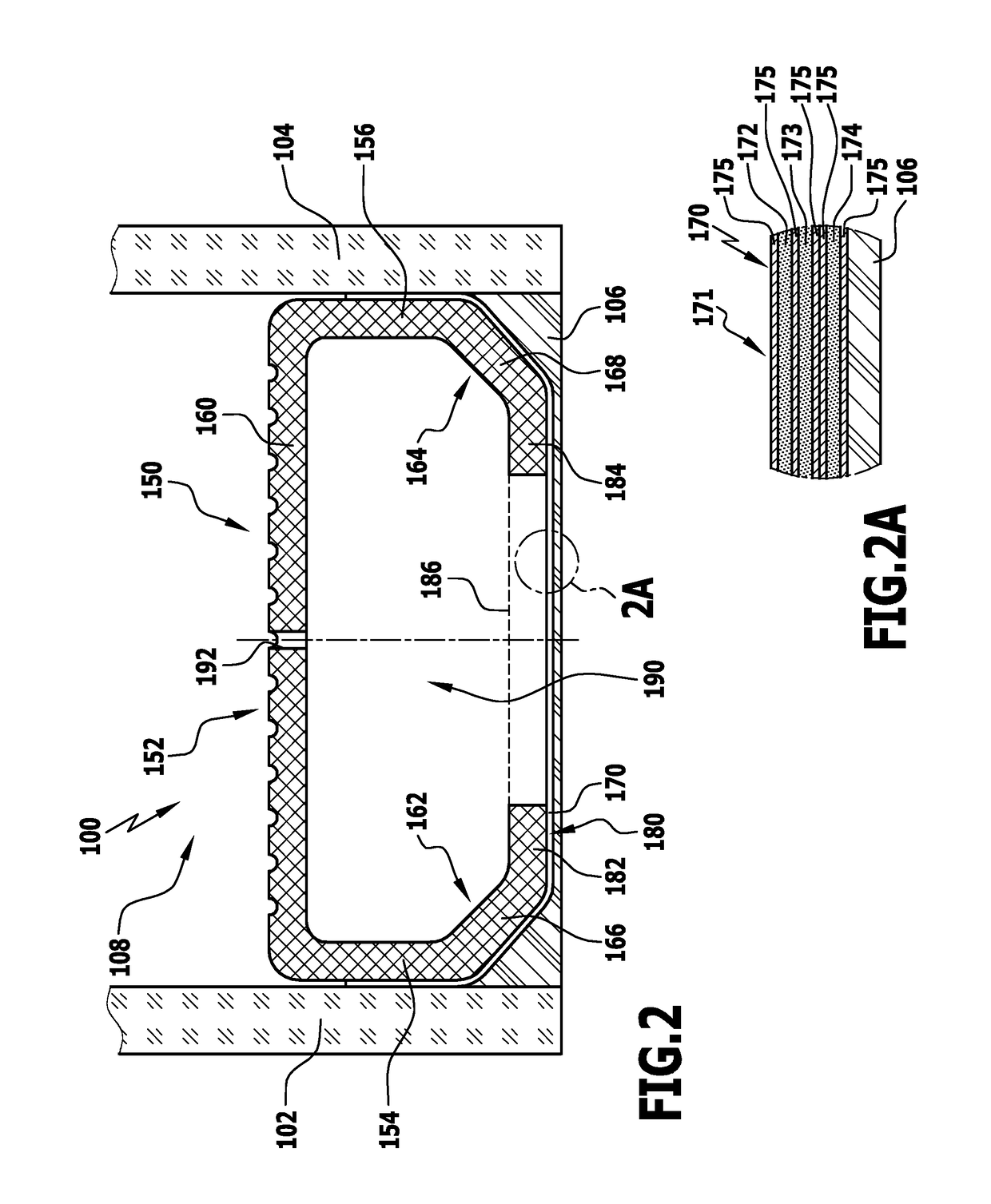
[0143]FIG. 2: a spacer in accordance with the invention in its installation situation in an insulating glass pane;

[0144]FIG. 2A: a variant of a polymer film as a vapor diffusion barrier of the spacer in accordance with the invention;

[0145]FIG. 3: a further embodiment of a spacer in accordance with the invention;

[0146]FIGS. 3A and 3B: further variants of the vapor diffusion barrier of a spacer in accordance with the invention;

[0147]FIG. 4: a further embodiment of a spacer in accordance with the invention;

[0148]FIG. 5: a further embodiment of a spacer in accordance with the invention;

[0149]FIG. 6: a possible variant of the outer wall of a spacer in accordance with the invention;

[0150]FIG. 7A to 7C: further variants of the outer wall of a spacer in accordance with the invention;

[0151]FIG. 8: A further variant of the outer wall of the spacer in accordance with the invention;

[0152]FIG. 9: a further variant of the outer wall of a spacer in accordance with the invention; and

[0153]FIG. 10: ...


PUM

PropertyMeasurementUnit
thicknessaaaaaaaaaa
thicknessaaaaaaaaaa
bending radiusaaaaaaaaaa

Abstract

A spacer for insulating glass panes comprises a profile body made using a first plastics material, which has a substantially U-shaped cross section with first and second side walls arranged in parallel, each having a free end and an inner wall extending between the first and the second side wall, and a vapor diffusion barrier made of a poorly heat conducting material, extending from the free end of the first side wall to the free end of the second side wall, wherein the vapor diffusion barrier is arranged substantially in parallel to and spaced apart from the inner wall. The profile body together with the vapor diffusion barrier encloses a cavity of the spacer which is optionally configured to accommodate a desiccant.

Description

CROSS-REFERENCE TO RELATED APPLICATIONS[0001]This patent application is a continuation of International Patent Application No. PCT / EP2016 / 076658, filed on Nov. 4, 2016, which claims the benefit of German Patent Application No. 10 2015 122 716.9, filed on Dec. 23, 2015, and 10 2016 115 023.1, filed on Aug. 12, 2016, which are incorporated herein by reference.BACKGROUND OF THE INVENTION[0002]The invention relates to a spacer for insulating glass panes, comprising a profile body made using a first plastics material, having a main body with a substantially U-shaped cross section with first and second side walls arranged in parallel and an inner wall extending between the first and the second side wall. The spacer further comprises a vapor diffusion barrier extending from a free end of the first side wall to a free end of the second side wall. Further, the vapor diffusion barrier is arranged substantially in parallel to and spaced apart from the inner wall.[0003]Spacers for insulating gl...

Claims


Application Information

Patent Timeline
Patent Type & Authority Applications(United States)
IPC IPC(8): E06B3/663
CPCE06B3/66319E06B2003/6638E06B2003/66395E06B2003/66385
Inventor RUNZE, PETERREHLING, MARCMOLLER, MICHAELKONIGSBERGER, BERNHARD
Owner ROLLTECH
Why Eureka
Eureka Blog
Learn More