
Firearm attachment locking systems and methods

a technology for locking systems and firearms, applied in the field of firearms, can solve the problems of suppressors not locking up in the same position, loose suppressors, etc., and achieve the effects of fast attachment, minimal effect of point-of-impact shift, and fast attachment and detachmen

Active Publication Date: 2018-03-20
RUGGED DESIGN INC
View PDF25 Cites 21 Cited by
  • Summary
  • Abstract
  • Description
  • Claims
  • Application Information

AI Technical Summary

Benefits of technology

The present patent relates to a system for quickly and securely attaching various muzzle attachments to firearms. It uses a rotating collar with a cam that locks the muzzle attachment device or suppressor interface when the collar is rotated. The system has minimal point-of-impact shift and uses surfaces to lock the suppressor to the muzzle device. A locking spring and one or more spring arms force it down against a surface on the muzzle attachment device. The attachment method is simple and requires screwing the suppressor or muzzle attachment onto the muzzle attachment device until it is securely locked up, then turning the rotating locking collar to lock the suppressor and the muzzle attachment device together, thus preventing the suppressor from moving during firing of the host firearm.

Problems solved by technology

Most of these systems have problems, and these relate to the use of ratchet systems used with spring biased secondary retention systems.
These problems include failure of the system to lock securely which leads to the suppressor becoming loose, as well as the suppressor failing to lock up in the same position when attached or re-attached.

Method used


Image

  • Firearm attachment locking systems and methods
  • Firearm attachment locking systems and methods
  • Firearm attachment locking systems and methods

Examples


Embodiment Construction

[0025]Herein the following definitions are used. “Forward” and “front” means towards the firing direction of the host rifle or suppressor (as shown in FIGS. 1-9 of the drawings as being on the right hand side of the drawings) while “rearward” or “rear” means the opposite direction from the firing direction (as shown in FIGS. 1-9 of the drawings as being on the left hand side of the drawings).

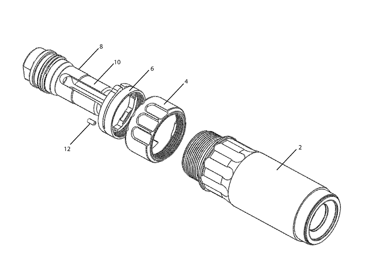
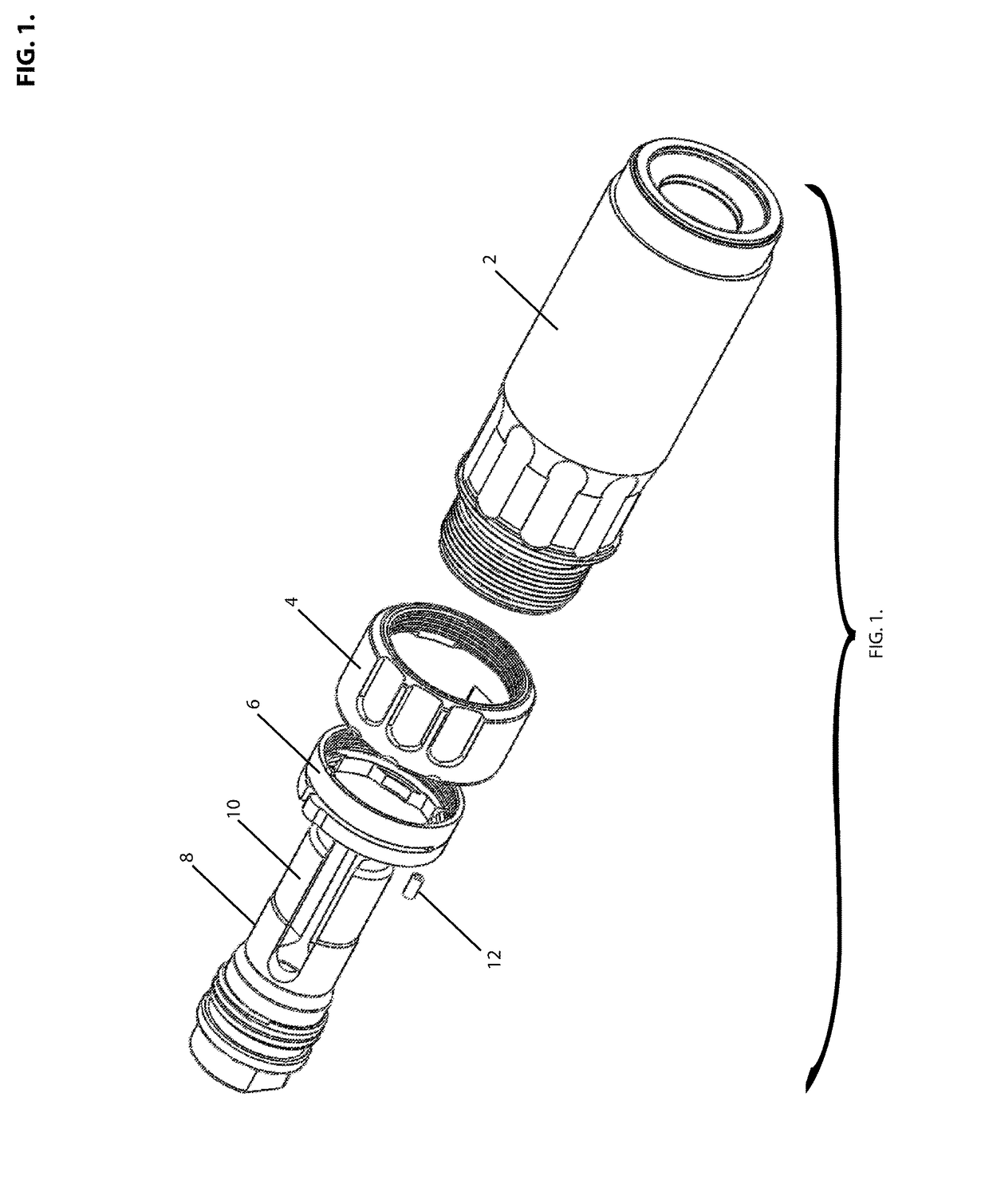
[0026]Referring to FIG. 1, the firearm attachment mount assembly 1 is shown in a disassembled view. The mount body 2 is shown with the rotating lock collar 4 and the locking spring 6. A muzzle attachment device 8 is shown and this is a flash hider 10 though a muzzle brake or a recoil compensator may be used in place of the flash hider. A locking pin 12 is shown and this is used for locking the rotating lock collar and the locking spring together when assembled.

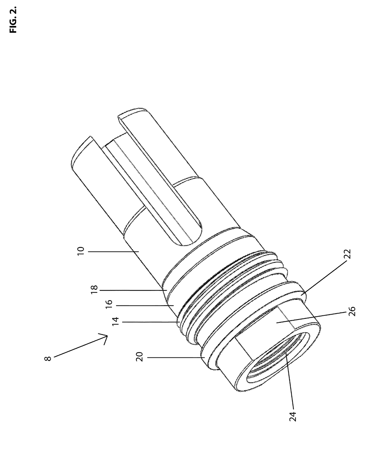
[0027]Referring to FIG. 2, a muzzle attachment device 8 is shown, and this is a flash hider 10. On the flash hider, there are external mo...


PUM


Abstract

The invention relates to devices for attaching or detaching a sound suppressor or an auxiliary device to a firearm. The device has a mount body that is attached by threads to a muzzle attachment device that is attached to the muzzle of a firearm. The muzzle attachment device has external mounting threads, a gas seal, an engagement surface, and a locking surface on the rear of the muzzle attachment device. The engagement surface simultaneously provides an alignment function and a forward locking function. A rotating collar is attached by threads to the mount body, and a locking spring with locking surfaces is attached to the mount body by threads, with the locking spring fitting inside the rotating collar. The rotating collar, when rotated, forces the locking spring and its locking surfaces downwards against the rear locking surface on the muzzle attachment device, providing force against the rear locking surface and securing the sound suppressor or auxiliary device to the muzzle attachment device through the combination of the forward engagement surface and the rear locking surface.

Description

BACKGROUND OF THE DISCLOSURE[0001]This application generally relates to firearms, and more specifically to systems for sound suppressors for attaching or removing a sound suppressor or other auxiliary device to the muzzle area of a firearm.[0002]The attachment to firearms of various muzzle attachments such as sound suppressors, blank firing adapters and other auxiliary muzzle attachments require that the muzzle attachment be secured to the firearm via a muzzle attachment device in a manner that is quick and secure. A prime requirement of a firearm attachment locking system is that the accuracy of the firearm should not be affected by the attachment or removal of the muzzle attachment. A good gas seal between the muzzle attachment and the muzzle attachment device is necessary and the method of attachment should be easy and intuitive to the user. The muzzle attachment device maybe a flash suppressor, a muzzle brake, a compensator or other devices that require attachment to a firearm's...

Claims


Application Information

Patent Timeline
IPC IPC(8): F41A21/32F41A21/30
CPCF41A21/325F41A21/30
Inventor GRAHAM, II, HENRY L.
Owner RUGGED DESIGN INC
Learn More