Device for producing radioisotopes

a radioisotope and device technology, applied in the direction of direct voltage accelerators, chemical to radiation conversion, accelerators, etc., can solve the problems of reducing the stopping power of the precursor and therefore the radioisotope production yield, the sealing of the irradiation cell, and the heat dissipation produced by the irradiation of the target material on such a small volume, so as to improve the cooling device

Active Publication Date: 2018-03-20
ION BEAM APPL
View PDF9 Cites 0 Cited by
  • Summary
  • Abstract
  • Description
  • Claims
  • Application Information

AI Technical Summary

Benefits of technology

[0020]a non-cryogenic cooling device for the walls of the cavity, capable of keeping at least one fraction (preferably all) of the target fluid comprised in the cavity in a liquid state when the target fluid is irradiated.The cavity comprises an inclined surface 15, defining the bottom of the cavity, so as to evacuate the target fluid, which condenses in contact with the walls of the cavity that are cooled by the cooling device, by gravity toward the metal foil. The inclined surface intersects the plane formed by the metal foil forming an acute angle (α) with the plane, so as to form, with the metal foil, a corner-shaped area capable of collecting the condensed target fluid by gravity. Due to the corner shape of that area, the height of the fluid collected therein is maximal at the metal foil and decreases moving away from the latter. This corner-shaped area ensures good cooling of the metal foil, in particular guaranteeing a maximum height of the fluid at the metal foil. The corner shape further reduces the risk of local overheating of the fluid, owing to excellent circulation of the fluid in that area by convection.

Problems solved by technology

Such a beam energy causes heating of the irradiation cell as well as vaporization of the radioisotope precursor, thereby decreasing the stopping power of that precursor and therefore the radioisotope production yield.
Furthermore, in the case of 18F production, due to the particularly high cost of the precursor, 18O-enriched water, only a very small volume of that precursor, at most several milliliters, can be placed in the irradiation cell.
Consequently, the issue of heat dissipation produced by the irradiation of the target material on such a small volume is a major problem to be overcome.
Such a device only enables the irradiation of small volumes of 18O-enriched water, and does not have the means making it possible to effectively cool the metal foil, which can be problematic in terms of the sealing of the irradiation cell.
Furthermore, the perforated grid is not completely transparent to the beam and prevents part of the beam from penetrating inside the cavity.
Part of the perforated grid or the metal foil therefore absorbs part of the beam, which causes heating of the metal foil.
The metal foil being relatively thin and being the most heated and least well-cooled part, it is relatively fragile.
Furthermore, the seals situated between the latter and the body are damaged during use and said cavity loses sealing.
A first drawback of this type of device is that when the irradiation cell is irradiated, a large portion of the fluid comprised in the cavity vaporizes, leaving only a thin net of water on the lower wall of the cavity.
Furthermore, the walls of the cavity being relatively thin and undergoing significant heating, said cavity collapses after several uses, which positions part of the liquid, which is already not very irradiated, outside the beam and causes a drop in yield.
The cooling of the fluid comprised in the cavity is therefore not optimal and must be improved so as to have more condensed liquid across from the beam so as to increase the probabilities of nuclear reactions.
Nevertheless, in this device, with the increase in the area of the foil exposed to the beam, the power of the beam dissipated in the foil nevertheless remains high, which causes overall heating of the foil and an increase in the inner pressure in the cavity.
Nevertheless, the device does not comprise a system for cooling the foil, and the addition of a pressurized chamber and therefore additional foil in the passage of the beam causes power losses of the beam.
The foil being poorly cooled, it is difficult to force the fluid against the apex of said foil.

Method used


Image

  • Device for producing radioisotopes
  • Device for producing radioisotopes
  • Device for producing radioisotopes

Examples


Embodiment Construction

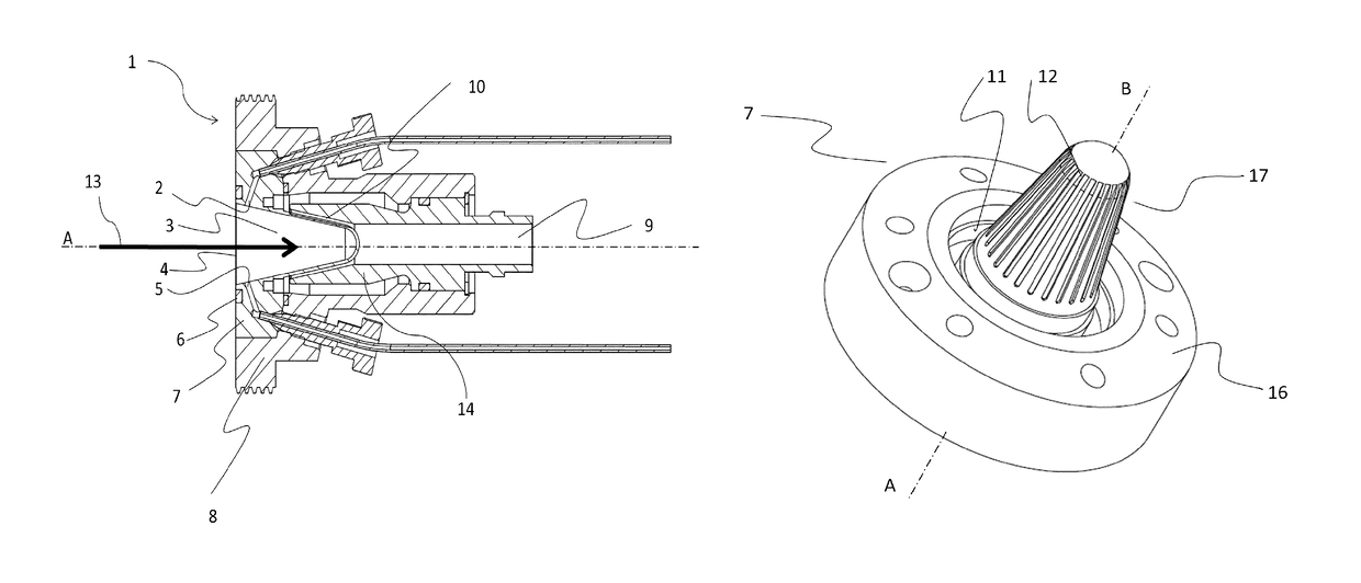
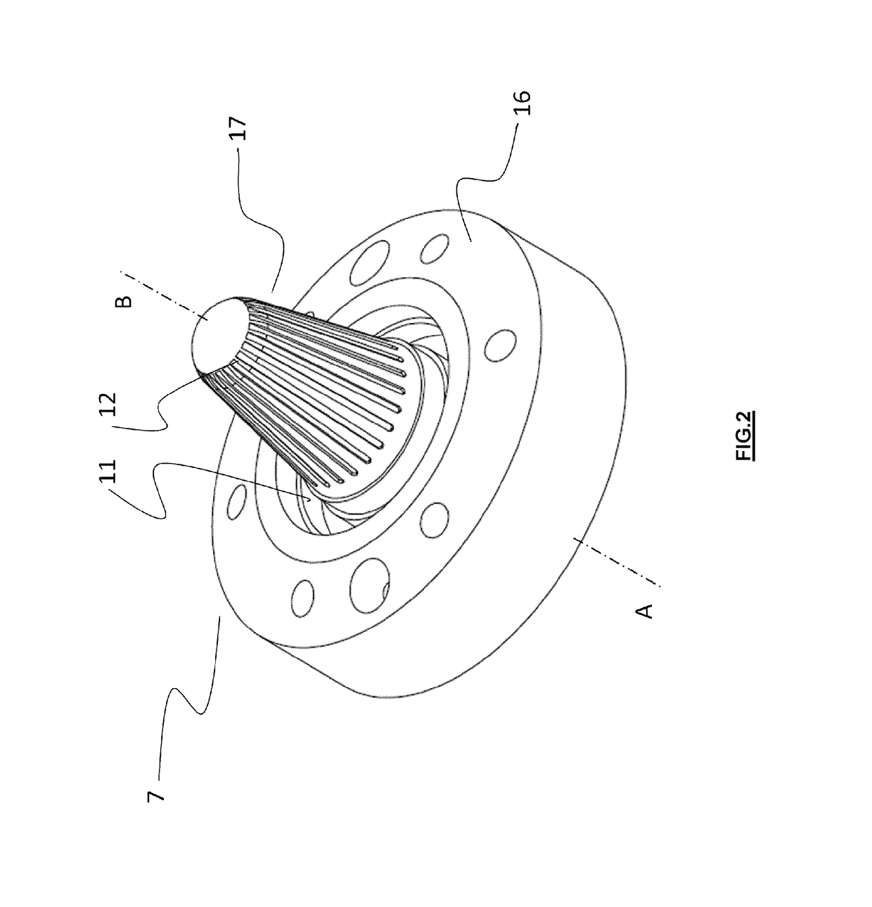
[0044]The device according to the present invention is designed to be used in the context of radioisotope production, in particular through irradiation of a target fluid using an accelerated particle beam. One preferred use of the device 1 according to the present invention is the production of 18F through bombardment using an accelerated proton beam 13 on 18O-enriched water. Preferably, the beam 13 is substantially horizontal.

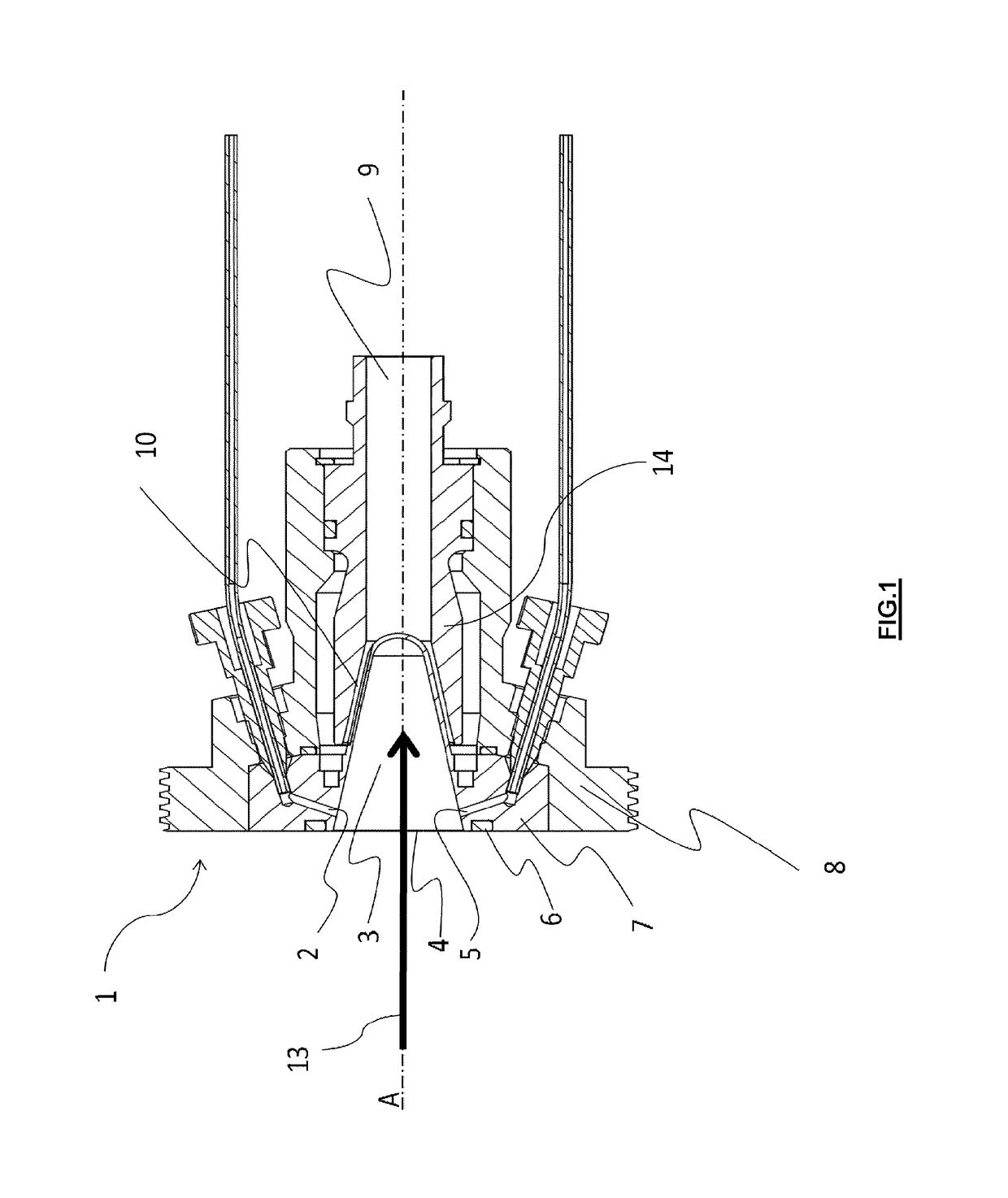
[0045]FIG. 1 shows a longitudinal cross-section of part of the device 1 according to one embodiment of the present invention. The device 1 of the present invention comprises an irradiation cell 7 shown in a three-dimensional view in FIG. 2. The irradiation cell 7 comprises a cavity 3 designed to contain a target fluid, for example 180-enriched water. As indicated in FIG. 3, the cavity 3 has an upper (or top) part 19 (located above the plane A-B) and a lower (or bottom) part 20 (located below the plane A-B). During operation, the plane A-B is substantially hori...


PUM


Abstract

The invention relates to a device (1) for producing radioisotopes by irradiating a target fluid using a particle beam (13). This device comprises an irradiation cell (7) that includes a cavity (3) for receiving the target fluid. A non-cryogenic cooling device cools the walls of the cavity (3). The cavity (3) has an inclined surface (15) downwardly delimiting the cavity (3) so as to evacuate the target fluid, which condenses on contact with the cooled walls, under gravity towards a metal foil (4) which closes off this cavity (3). The inclined surface (15) intersects the plane formed by the metal foil (4), making an acute angle (a) with said plane, so as to form with the metal foil (4) a wedge-shaped zone (18) capable of collecting, by gravity, the condensed target fluid.

Description

CROSS REFERENCE TO RELATED APPLICATIONS[0001]This application is a national phase application of International Application No. PCT / EP2011 / 068876, filed Oct. 27, 2011, designating the United States and claiming priority to Belgium Patent Application No. 2010 / 0640, filed Oct. 27, 2010, both of which are incorporated by reference as if fully rewritten herein.TECHNICAL FIELD[0002]The present invention generally relates to a device for producing radioisotopes, and more particularly a device for producing radioisotopes through radiation using a particle beam of a target fluid comprising a radioisotope precursor. It also relates to an irradiation cell designed to produce radioisotopes through irradiation using a particle beam of a target fluid comprising a radioisotope precursor.BACKGROUND OF THE INVENTION[0003]In nuclear medicine, positron emission tomography is an imaging technique requiring radioisotopes imaging positrons or molecules marked by those same radioisotopes. 18F is one of th...

Claims


Application Information

Patent Timeline
Patent Type & Authority Patents(United States)
IPC IPC(8): G21G1/10H05H6/00G21G4/04G21G1/00
CPCG21G4/04H05H6/00G21G1/10G21G2001/0015
Inventor LAMBERT, BERNARDGEETS, JEAN-MICHELCAMBRIANI, ANDREADEGEYTER, MICHELKISELEV, MAXIM
Owner ION BEAM APPL
Why Eureka
Try Eureka