Magnetic separator and release tool therefor

a technology of magnetic separator and release tool, which is applied in the direction of centrifugal force sediment separation, sedimentation settling tank feed/discharge, sedimentation settling tank discharge, etc., can solve problems such as property damage, and achieve the effect of limiting the possibility of accidental releas

Active Publication Date: 2018-04-03
ADEY HLDG
View PDF24 Cites 0 Cited by
  • Summary
  • Abstract
  • Description
  • Claims
  • Application Information

AI Technical Summary

Benefits of technology

[0015]A locking member may be provided, for locking the release tool in a position where force cannot be transmitted to the collets via the bearing areas. The locking member may engage with part of the separator housing, preventing further movement of the release tool towards the housing.
[0038]The raised flat surface formed by the extension provides a flat bearing surface for the locking member of the release tool of the third aspect of the invention. A locking member bearing against a curved surface would have a small contact area, and hence exert considerable pressure on the curved housing, risking damage. Providing a flat bearing surface increases the contact area, reduces the pressure, and limits the possibility of the housing being damaged by a locking member.

Problems solved by technology

Such accidental release would be highly undesirable since a large amount of dirty water may be released from the heating circuit, causing damage to property.

Method used


Image

  • Magnetic separator and release tool therefor
  • Magnetic separator and release tool therefor
  • Magnetic separator and release tool therefor

Examples


second embodiment

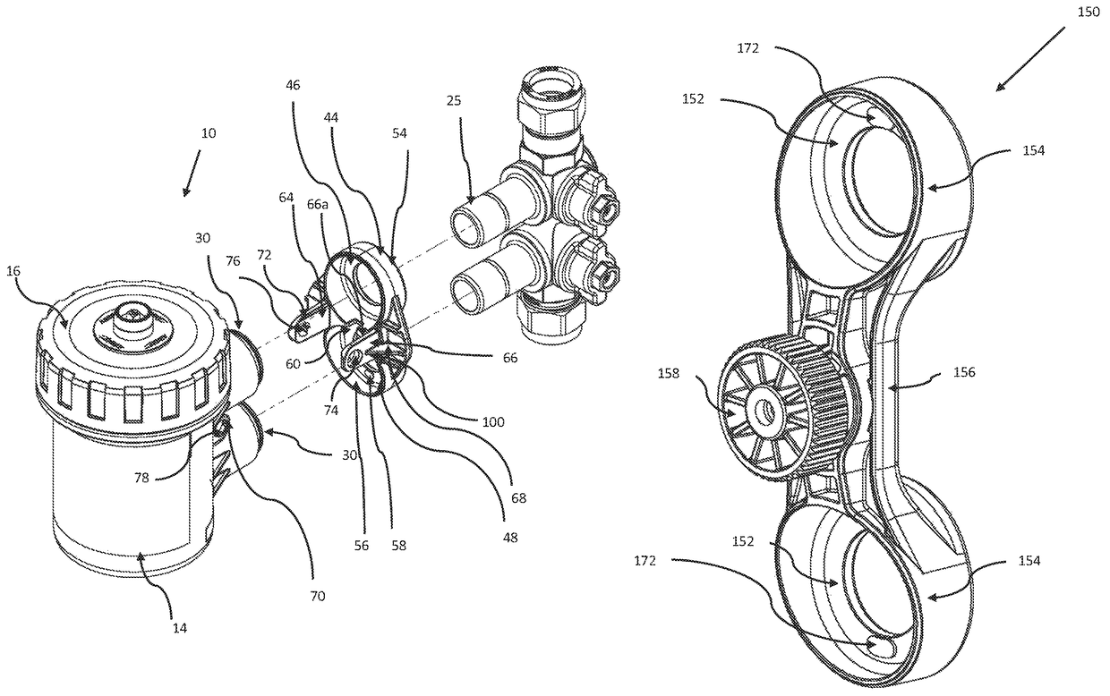
[0067]Referring now to FIGS. 7 to 11, release tool for use with separator device 110 is shown generally at 150. The release tool 150 comprises two circular discs 152, each having a circular aperture at its centre, a wall 154 extending from the edge of each disc 152, and a connecting handle member 156 between the discs 152. A circular locking member 158 includes a female threaded section through its centre, and a corresponding male threaded section 160 extends perpendicularly from the connecting member 156. The circular locking member 158 is screwed on to the male threaded section 160, the distance between the locking member 158 and the connecting handle member 156 being adjustable by rotating the locking member 158 to move it along the male threaded section 160.

[0068]JOHN GUEST SPEEDFIT® connectors 98 on the inlet and outlet 96 of the separator device 110 include collets 99, which when pushed towards the body of the separator device 10 allow the separator device 10 to be released fr...

first embodiment

[0071]As seen best in FIG. 8, the release tool 150 includes raised areas 172 on outer edges of the bearing areas 152, as in the The raised areas ensure that even force is provided on either side of the collets 99 in use. The release tool 150 is slightly curved and also may deform very slightly in use, the outer edges (furthest from the handle portion) bending away from the direction of the force applied to the handle portion. The raised areas 172 compensate for this, ensuring that the release tool pivots against the outer edges of the collets rather than the inner edges, so that the inner edge pushes into the collet when force is applied, rather than the outer edge moving away from the collet. In this way an even force is applied across opposing sides of the connectors and they release easily.

[0072]The release tools disclosed allow for secure fitting and yet easy release of the separator devices 10, 110. Because the separator devices 10, 110 may easily be completely removed from th...


PUM

PropertyMeasurementUnit
depthaaaaaaaaaa
depthaaaaaaaaaa
depthaaaaaaaaaa

Abstract

A magnetic separator for a central heating system comprises a housing, a separation chamber within the housing, and inlet and outlet ports extending from the housing. The inlet and outlet ports include push-fit connectors having collets surrounding the mouth of each of the inlet and outlet for releasing the connectors. The magnetic separator also has a release tool. The release tool has first and second bearing areas for bearing against the collets of the inlet and outlet connectors, and a handle region for enabling force to be applied, via the bearing areas, to both connectors simultaneously.

Description

CROSS-REFERENCE TO RELATED APPLICATIONS[0001]This application is a National Stage of International Application No. PCT / GB2013 / 052880, filed Nov. 4, 2013, which claims priority to GB 1317652.4, filed Oct. 7, 2013, and to International Application No. PCT / GB2013 / 051329 and International Application No. PCT / GB2013 / 051330, both filed May 21, 2013, and also to GB 1219752.1, filed on Nov. 2, 2012. The entire disclosures of the above applications are hereby incorporated herein by reference.FIELD OF THE INVENTION[0002]The present invention relates to a magnetic separator for use in a central heating system and in particular to a magnetic separator release tool.BACKGROUND TO THE INVENTION[0003]Magnetic separators are now widely fitted to domestic and commercial central heating systems. The separators remove debris, and particularly magnetic debris, from the heating fluid. This keeps the heating fluid clean, preventing build-up of debris in, for example, the boiler, where it may cause expensi...

Claims


Application Information

Patent Timeline
Patent Type & Authority Patents(United States)
IPC IPC(8): B04C5/14E03B7/07B04C3/06B04C5/185B01D21/26F16L29/00F16L21/00B03C1/30B03C1/14C02F1/48B03C1/02B01D21/24F16L55/24B01D21/00B01D29/90F24D19/00F17D3/16B03C1/28B03C1/0355B21D39/04B01D35/30B01D35/06C02F101/20
CPCB03C1/30B03C1/288B04C5/185B21D39/044C02F1/488E03B7/074F16L21/00F16L29/007F17D3/16F24D19/0092B04C5/14B01D21/0009B01D21/2411B01D21/2483B01D21/26B01D21/267B01D29/908B01D35/06B01D35/303B03C1/02B03C1/0355B03C1/14B03C1/286B04C3/06B01D21/0042B01D2201/302B01D2201/4023B01D2221/02B03C2201/18B03C2201/20B03C2201/28C02F2101/203C02F2201/48C02F2303/22F16L55/24Y10T137/794Y02B30/00B01D21/00B01D21/003B01D21/0036B01D21/0039B01D21/0045B01D21/0066B01D21/0087B01D21/0024B03C1/28B25B11/02B25B13/48B25B13/481B01D21/24B01D29/90E03B7/07F24D19/00B01D35/30Y02W10/10
Inventor ADEY, CHRISTOPHERTAYLOR, MATTHEWDOWNIE, SIMONPATHAN, KASHEM
Owner ADEY HLDG
Why Eureka
Try Eureka