
Dual shaving razor assembly and case therefor

a dual-shaver and assembly technology, applied in the field of shaving razors, can solve the problems of increasing the occurrence of nicks and cuts on the skin, difficult control of shaving operation, and difficulty in shaveing, so as to facilitate the use and manufacture, facilitate transportation, and hold the dual-shaver assembly safely.

Active Publication Date: 2018-04-03
SPEED RAZOR CORP
View PDF56 Cites 5 Cited by
  • Summary
  • Abstract
  • Description
  • Claims
  • Application Information

AI Technical Summary

Benefits of technology

The present invention provides a dual shaving razor assembly with the following technical effects: each shaving cartridge can rotate separately to accommodate skin orientation without applying undue pressure to the skin, the two shaving cartridges can rotate relative to each other, the case can safely hold the dual shaving razor assembly without damage to the blades of the shaving cartridges and can easily transport, the dual shaving razor assembly is easy and economical to use and manufacture. Additionally, the invention includes a mechanism for removably securing the cover to the base, which includes recesses on the base and tabs on the cover for easy assembly.

Problems solved by technology

However, because of this arrangement, the razor can only shave in one direction at a time.
As a result, it is more difficult to control the shaving operation.
Still further, each time the razor is raised up from the skin and placed down on another location of the skin for shaving, the occurrence of nicks and cuts on the skin becomes greater.
However, with such known dual shaving razor assemblies, the angles and orientations of the razor heads cannot be satisfactorily controlled.
This arrangement has the disadvantage that a relatively large pressure must be applied to the flexible arch.
This large pressure, in turn, results in a large pressure being applied to the shaving cartridges, which is disadvantageous from a shaving perspective.
As a result, a large amount of pressure is applied to the shaving cartridges.
In addition, this patent publication is limited in that both shaving cartridges must be rotated at the same time with the same pressure.
Lastly, because of the unitary body construction of the flexible arch, there is no transverse rotation of the shaving cartridges relative to each other, thereby providing even less shaving control.
As discussed above, such an operation results in nicks and cuts on the skin.
Further, since the shaving cartridges in this patent publication do not rotate relative to the main body, control of the shaving operation, and particularly, the orientation of the shaving cartridges and pressure applied, is restricted, producing a less than desirable shaving operation.
Thus, this patent publication still suffers from the deficiencies of PCT Patent Publication No.

Method used


Image

  • Dual shaving razor assembly and case therefor
  • Dual shaving razor assembly and case therefor
  • Dual shaving razor assembly and case therefor

Examples


first embodiment

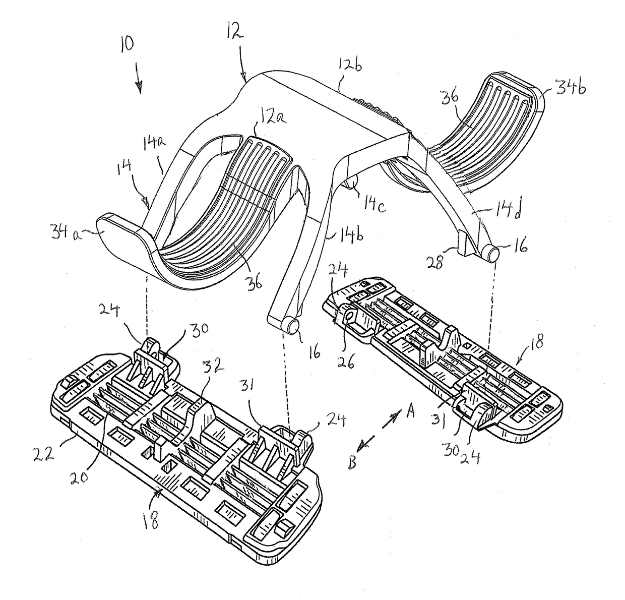
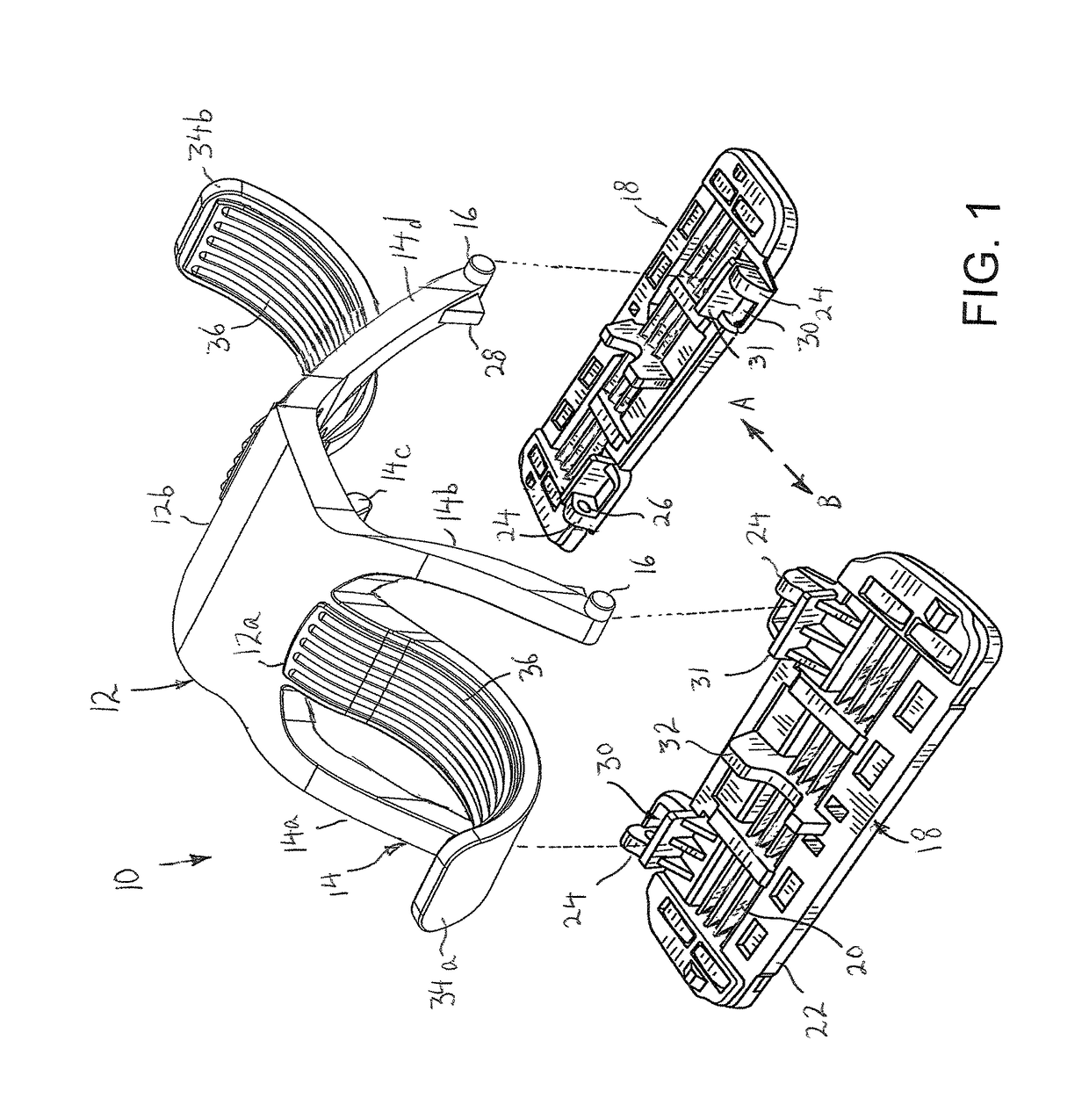
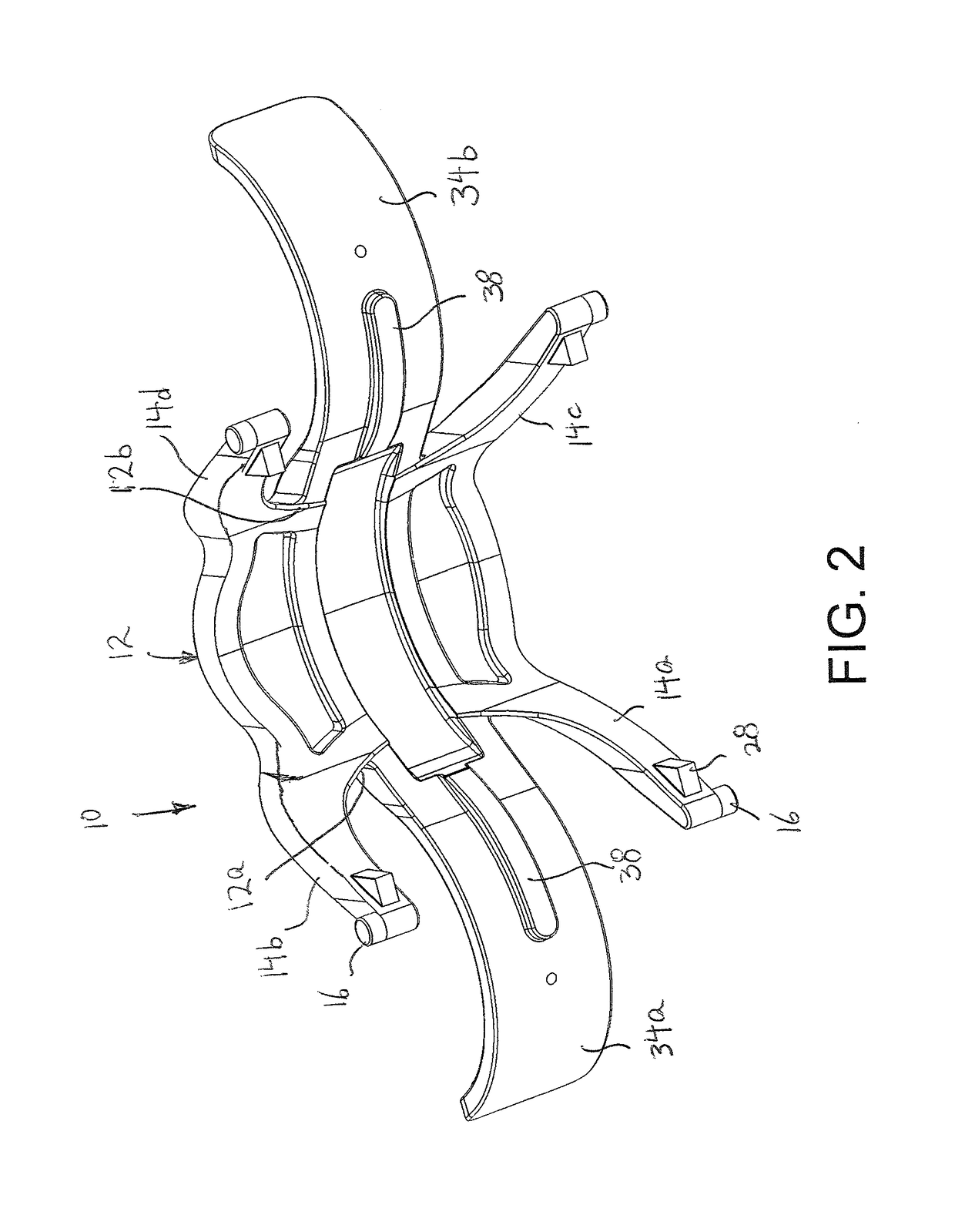
[0063]Referring initially to FIGS. 1-5, there is shown a dual shaving razor assembly 10 according to the present invention. Dual shaving razor assembly 10 includes a main arch-like body 12, preferably having a square or rectangular shape with straight or rounded side edges, although the present invention is not limited to the shape. Main body 12 is curved from front to back so as to have an upwardly bowed configuration.

[0064]Four legs 14 extend from the corners of main body 12 in a downwardly angled manner of about 45°. Each leg 14 is also preferably slightly outwardly curved or bowed, as shown best in FIGS. 3 and 4, for better stability of dual shaving razor assembly 10 on the skin of a person. Specifically, there are two spaced apart legs 14a and 14b extending forwardly from the corners at the front edge 12a of main body 12, and two spaced apart legs 14c and 14d extending rearwardly from the corners at the rear edge 12b of main body 12. A cylindrical peg 16 extends outwardly from ...

second embodiment

[0083]Referring now to FIGS. 6-15, there is shown a dual shaving razor assembly 110 according to the present invention. Dual shaving razor assembly 110 is constructed in the same manner as dual shaving razor assembly 10, except as indicated below, and common elements thereof are referred to by the same reference numerals.

[0084]Dual shaving razor assembly 110 differs from dual shaving razor assembly 10 by forming main arch-like body 112 into two body segments 112a and 112b which are pivotally connected to each other for transverse pivoting rotation, in order to provide more accurate and more controlled shaving, whereby shaving cartridges 18 more accurately adapt to the contour of skin surface.

[0085]In this regard, body segments 112a and 112b have inner planar surfaces 113a and 113b, respectively, that abut at a transverse centerline 115. In order to pivotally connect body segments 112a and 112b, body segment 112a includes a cylindrical projection 117 extending centrally out from plan...

third embodiment

[0090]Referring now to FIGS. 16-19, there is shown a dual shaving razor assembly 210 according to the present invention. Dual shaving razor assembly 210 is constructed in the same manner as dual shaving razor assembly 110, except as indicated below, and common elements thereof are referred to by the same reference numerals.

[0091]Dual shaving razor assembly 210 differs from dual shaving razor assembly 110 in the manner that body segments 212a and 212b are pivotally connected together.

[0092]As with dual shaving razor assembly 110, dual shaving razor assembly 210 includes a main arch-like body 212 formed by two body segments 212a and 212b which are pivotally connected to each other for transverse pivoting rotation, in order to provide more accurate and more controlled shaving, whereby shaving cartridges 18 more accurately adapt to the contour of skin surface. In this regard, body segments 212a and 212b have inner planar surfaces 213a and 213b, respectively, that abut at a transverse ce...


PUM


Abstract

A dual shaving razor assembly includes an arched central main body and first and second pairs of legs extending down from first and second sides of the main body, respectively, the legs of each pair being in spaced relation to each other. Each pair includes a securing arrangement for securing a shaving cartridge having blades thereto such that each shaving cartridge is adapted to pivot relative to the main body. First and second flexible and resilient wings extend from the first and second sides, respectively, of the main body between the first and second pairs of legs to a position immediately above a respective shaving cartridge held by the respective pair of legs. The wings are adapted to engage an upper surface of the respective cartridge to pivot the shaving cartridge relative to the main body upon application of an external force to the respective flexible and resilient wing.

Description

BACKGROUND OF THE INVENTION[0001]The present invention relates generally to shaving razors, and more particularly, to a dual razor assembly having to razor heads at opposite ends of the assembly.[0002]Conventionally, a manual shaver includes a handle and a shaving head at one end of the handle, with the shaving head adapted to hold a razor assembly therein. The razor assembly can hold one or more parallel blades for shaving purposes. For example, two or more parallel blades may be mounted one behind the other for the purpose of producing a closer shave. However, because of this arrangement, the razor can only shave in one direction at a time.[0003]Further, because such razors are held by the handle during shaving, the force applied by the shaving head on the skin is a result of a torque or moment of force, rather than a direct force on the razor head. As a result, it is more difficult to control the shaving operation.[0004]Still further, each time the razor is raised up from the ski...

Claims


Application Information

Patent Timeline
Patent Type & Authority Patents(United States)
IPC IPC(8): B26B19/00B26B19/44B26B21/22B26B21/40B26B21/52
CPCB26B21/225B26B21/40B26B21/522
Inventor SCHMIDT, KEVIN
Owner SPEED RAZOR CORP
Learn More