Passive grease trap using separator technology

a separator and grease technology, applied in sedimentation settling tanks, separation processes, containers, etc., can solve the problems of waste to be expelled with grey water, intrusion and inconvenient for businesses, and waste tends to build up inside the tank

Active Publication Date: 2018-04-03
THERMACO INC
View PDF89 Cites 13 Cited by
  • Summary
  • Abstract
  • Description
  • Claims
  • Application Information

AI Technical Summary

Benefits of technology

[0005]In an embodiment, the tank is roto-molded plastic. Preferably, the baffle is positioned above an inlet invert opening and an outlet invert opening, and the baffle and the downwardly shaped bottom of the outer tank diverge so waste water entering the lower chambers encounters an enlarging volume. In one example, the tank may be an increased capacity tank. In another example the tank may have a length and a width. In one example, the tank length may be greater than the tank width. A baffle insert may extend the length of an increased capacity tank.
[0010]In another embodiment, a method of separating lightweight grease and heavy solids from wastewater includes supplying the wastewater into a grease trap through an inlet invert opening into a lower chamber, and allowing grey water to exit the grease trap through an outlet invert, thereby establishing at least intermittent currents from the inlet invert to the outlet invert. The method may include allowing grease in the waste water to rise by gravity from the lower chamber through a hole in a baffle insert and into an upper chamber so the grease is sequestered in the upper chamber and protected from entrainment in currents of grey water, and allowing heavy solids in the waste water to fall by gravity to a sump in the lower chamber. Finally, the method may include removing collected grease and heavy solids from the grease trap.

Problems solved by technology

Passive grease traps are usually emptied less regularly than automatic grease traps and therefore waste tends to build up inside the tank.
A problem with many grease traps is that water may flush through the system with such velocity that it disrupts the grease that has already separated, causing the waste to be expelled with grey water.
Emptying the grease from the passive traps typically has to be scheduled and can be intrusive and inconvenient for businesses.
Grease traps are often not easily accessible for grease removal and FOG accumulation on the trap parts can make grease removal even more difficult.
Such traps can be difficult to originally position and also to repetitively access when grease removal is needed.
As such, grease traps, though effective to remove some grease and solid waste from solids containing liquids, may not adequately prevent grease from going downstream with the water and remain challenging for grease removal.

Method used


Image

  • Passive grease trap using separator technology
  • Passive grease trap using separator technology
  • Passive grease trap using separator technology

Examples


Embodiment Construction

[0027]In the following description, like reference characters designate like or corresponding parts throughout the several views. Also in the following description, it is to be understood that such terms as “forward,”“rearward,”“left,”“right,”“upwardly,”“downwardly,” and the like are words of convenience and are not to be construed as limiting terms.

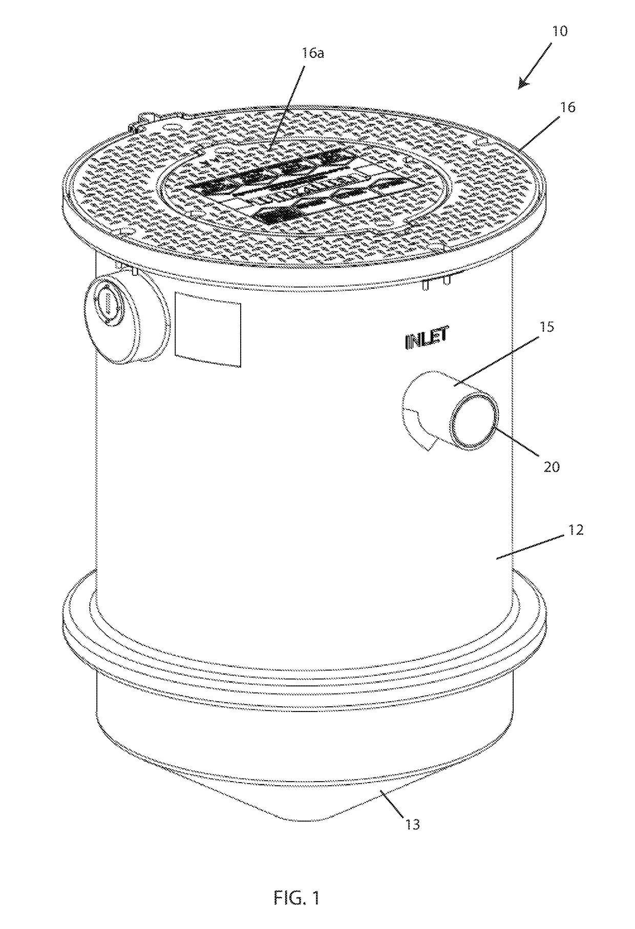
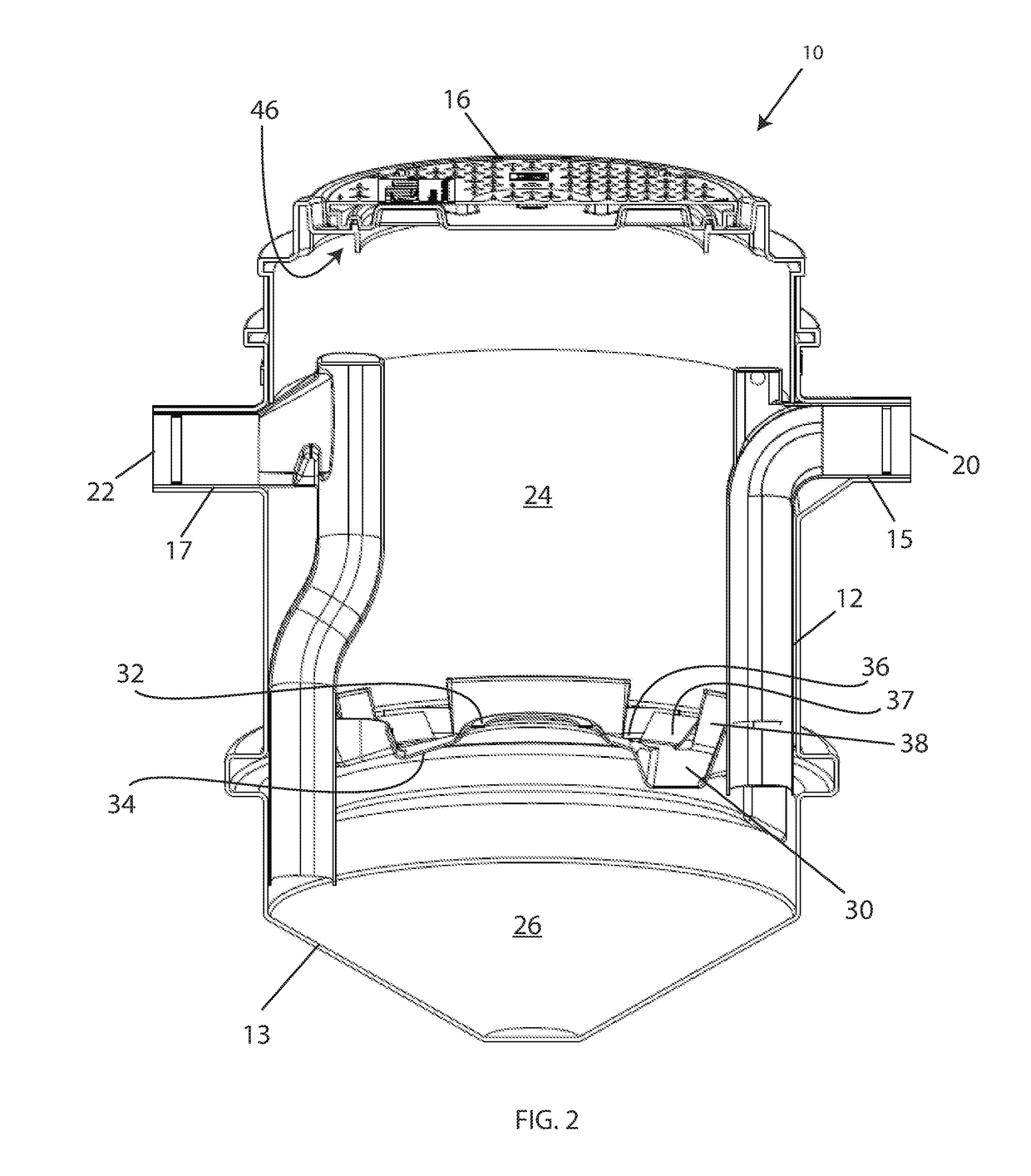
[0028]Referring now to the drawings in general and FIGS. 1 and 2 in particular, it will be understood that the illustrations are for the purpose of describing embodiments of the disclosure and are not intended to limit the disclosure or any invention thereto.

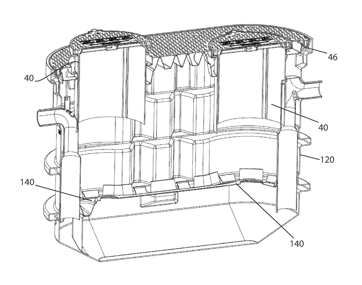
[0029]FIGS. 1 and 2 show a grease trap 10 for separating solids and grease from waste water. The grease trap 10 includes a tank 12 with a downwardly shaped bottom 13. In this embodiment, the downwardly shaped bottom is shaped like an inverted pyramid, but other shapes such as a conical shape, bowl shape, slanted plane, or the like, can be used. Preferably, the lowermost portion is ce...


PUM

PropertyMeasurementUnit
heightaaaaaaaaaa
heightaaaaaaaaaa
circumferenceaaaaaaaaaa

Abstract

An apparatus and method for a grease trap for separating grease and solid waste from waste water. The grease trap includes a tank having a downwardly shaped bottom. An upwardly shaped baffle insert divides the tank into an upper chamber and a lower chamber. An outlet port near an upper part of the baffle allows waste into the upper chamber. An inlet invert in the tank receives incoming waste water, while an outlet invert removes water from the tank. A removable cover covers the tank and allows access for removal of accumulated grease and solid wastes.

Description

BACKGROUND[0001]Historically, grease traps have been used in restaurants and other commercial facilities to limit the amount of grease and solid waste that is carried into sewer systems via waste water. Typical grease traps are either passive grease traps or automatic grease traps. Passive grease traps are usually emptied less regularly than automatic grease traps and therefore waste tends to build up inside the tank. Passive grease traps typically include a tank with an inlet that brings in waste water and an outlet that carries water out of the system. Lightweight grease rises to the top of the tank and heavier solids settle in the bottom of the tank.[0002]A problem with many grease traps is that water may flush through the system with such velocity that it disrupts the grease that has already separated, causing the waste to be expelled with grey water. This is especially true as the tank fills up with grease, so that the grease / water interface is closer to the grease trap bottom....

Claims


Application Information

Patent Timeline
Patent Type & Authority Patents(United States)
IPC IPC(8): C02F1/40B01D17/028B01D21/00B01D21/02B01D21/24B01D17/02E03F5/16C02F1/00C02F101/32C02F103/32
CPCC02F1/40B01D21/0042B01D21/10B01D21/245B01D17/0214E03F5/16B01D17/0211C02F2001/007C02F2101/32C02F2103/32C02F2201/002B01D21/2433B01D21/2483B65D90/105
Inventor BATTEN, WILLIAM C.KYLES, BRUCE W.PROCHNAU, KENNETH KAIE
Owner THERMACO INC
Why Eureka
Try Eureka