Method and apparatus for flow regulation

a flow regulator and flow rate technology, applied in the direction of process and machine control, transportation and packaging, instruments, etc., can solve the problems of reducing the flow rate, and unable to achieve the correct water to syrup ratio of beverage dispensers, so as to prevent further rotational deformation of the flow washer, and reduce the size of the orifice

Active Publication Date: 2018-04-03
LANCER PARTNERSHIP
View PDF26 Cites 0 Cited by
  • Summary
  • Abstract
  • Description
  • Claims
  • Application Information

AI Technical Summary

Benefits of technology

[0011]Once the flow regulator system is placed within the fluid flow path, fluid flowing through the fluid flow path contacts the flow washer. In contacting the flow washer, the fluid strikes the inlet surface of the plate creating pressure on the plate. In particular, pressure created on the inlet surface of the plate forces fluid through the orifice of the flow washer and into the delivery path. Fluid entering the delivery path fills the circumferential channel such that the fluid equalizes fluid pressure within the cavity of the flow washer. Equal pressure within the cavity of the flow washer stabilizes the flow of fluid through the flow washer and prevents vibration of the flow washer within the flow washer seat. Furthermore, fluid collected in the circumferential channel enters the fluid conduit inlet for conveyance to the fluid conduit outlet via the fluid conduit.
[0014]In addition, to the above-stated features, the diffuser of the diffuser assembly may be adjustable such that the diffuser may extend or retract into the orifice of the flow washer. Specifically, the regulator body includes a fluid chamber communicating with the fluid conduit outlet of the fluid conduit and the diffuser assembly includes a base installed within the fluid chamber. The base is linearly adjustable within the fluid chamber such that linearly adjusting the base extends or retracts the diffuser. More particularly, the diffuser includes a shaft disposed within the base and a tip such that linear adjustment of the base either extends or retracts the tip into the orifice of the flow washer. Extending the tip of the diffuser into the orifice decreases the fluid flow rate within the fluid flow path. Conversely, retracting the tip from the orifice of the flow washer increases the fluid flow rate within the fluid flow path.

Problems solved by technology

In many applications, flow washers are limited in their use because they can only regulate the flow rates of fluids over a limited range of pressures.
For example, in a typical flow washer, the operating range of the flow washer with respect to pressure is limited, and, once the pressure increases beyond the operating range, the flow rate rapidly decreases.
Maintaining the correct water to syrup ratio can be difficult to achieve for beverage dispensers.
For example, water pressure varies depending upon location and also may be affected by the number of users dispensing a drink from a beverage dispenser.
However, ceramic flow regulators are expensive to manufacture.

Method used


Image

  • Method and apparatus for flow regulation
  • Method and apparatus for flow regulation
  • Method and apparatus for flow regulation

Examples


Embodiment Construction

[0038]As required, detailed embodiments of the present invention are disclosed herein; however, it is to be understood that the disclosed embodiments are merely exemplary of the invention, which may be embodied in various forms. Figures are not necessarily to scale, and some features may be exaggerated to show details of particular components or steps.

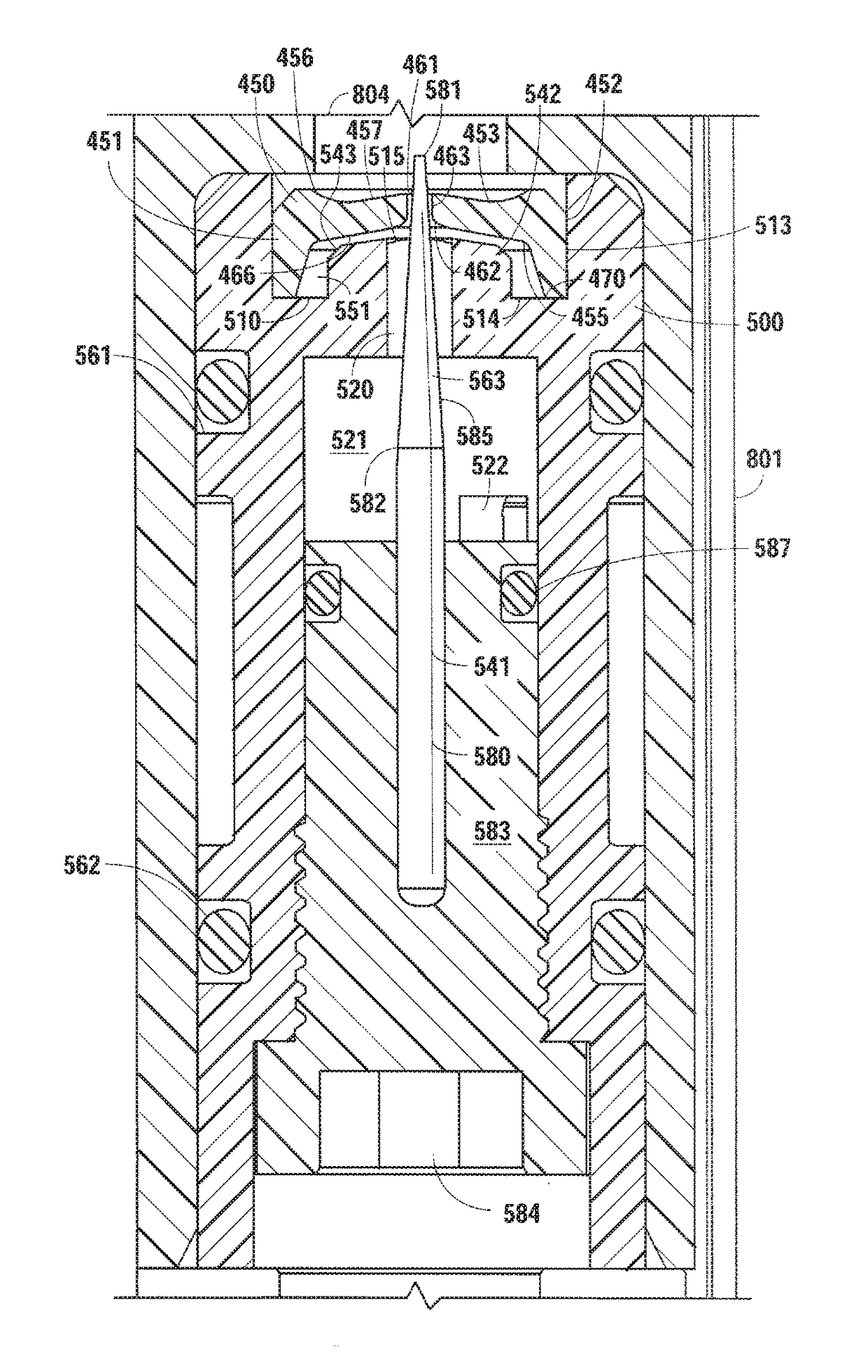
[0039]FIGS. 4-6 illustrate modular flow regulator system 1 including a flow regulator 200 and a flow regulator 400. The flow regulator 200 and the flow regulator 400 of the modular flow regulator system 1 are in fluid communication with a fluid flow path 700 and 800. In particular, the flow regulator 200 inserts within a housing 701 that is within the fluid flow path 700 and the flow regulator 400 inserts within a housing 801 that is within the fluid flow path 800. The fluid flow path 700 receives fluid from a fluid source 702 that flows through a fluid line 703 and into an inlet 704 in the housing 701. From the inlet 704 the fluid flo...


PUM


Abstract

A flow regulator system includes a flow regulator placed within a fluid flow path to maintain fluid flow therethrough at a desired flow rate. The flow regulator includes a flow washer having an orifice therethrough and a regulator body that receives the flow washer. At fluid pressures between a first fluid pressure and a second fluid pressure, the flow washer rotationally deforms to decrease or increase the size of the orifice, thereby maintaining the desired flow rate. When fluid pressure is greater than or equal to the second fluid pressure, the flow washer contacts a portion of the regulator body to prevent further rotational deformation of the flow washer. In addition, the flow washer radially compresses or expands to increase or decrease the size of the orifice, thereby maintaining the desired flow rate.

Description

BACKGROUND OF THE INVENTION[0001]1. Field of the Invention[0002]The present invention relates generally to flow regulators, and, more particularly, but not by way of limitation, to flow regulators that incorporate a flow washer to maintain a desired flow rate over a greater range of fluid pressures.[0003]2. Description of the Related Art[0004]Flow regulators are used in many applications to control the flow rate of fluid through a conduit such that the flow rate of the fluid is uniform under varying pressure conditions. In many flow regulators, flow washers are incorporated for the purpose of maintaining flow rate. Flow washers are typically discs constructed of a flexible resilient material that have a central orifice extending therethrough. The central orifice of the flow washer distorts to different diameters under different pressure conditions. Specifically, the size of the diameter of the orifice reduces as the source pressure is elevated.[0005]FIGS. 1 and 2 illustrate a flow w...

Claims


Application Information

Patent Timeline
Patent Type & Authority Patents(United States)
IPC IPC(8): F15D1/02G05D11/03G05D7/01B67D1/12
CPCG05D11/03G05D7/012B67D1/1281
Inventor SMELLER, DONALD W.
Owner LANCER PARTNERSHIP
Why Eureka
Try Eureka