Poultry feed distribution system with feeding devices having rotatable attachment parts with drop tubes hingedly connected thereto

a technology of poultry feed and distribution system, which is applied in the direction of cleaning process and apparatus, cleaning using liquids, aviculture, etc., can solve the problems of difficult and time-consuming to remove all the dispensing pans from the devices, difficult and time-consuming to place the pans back again after they have been cleaned, and somewhat difficult to clean. , to achieve the effect of reducing the cleaning efficiency of poultry feed distribution system

Active Publication Date: 2018-04-10
ROXELL
View PDF12 Cites 0 Cited by
  • Summary
  • Abstract
  • Description
  • Claims
  • Application Information

AI Technical Summary

Benefits of technology

[0012]The present invention aims to overcome the abovementioned disadvantages at least partly, or to provide a usable alternative. In particular the invention aims to make a true difference in the cleaning efficiency of poultry feed distribution systems, while at the same time making the system even more user friendly without making it vulnerable, heavy or expensive.
[0014]Thus the feeding devices can be thoroughly cleaned in their entirety. A farmer can now even hose clean the inside of the drop tube without running the risk of dirt being blown towards and leaving behind at blind spots inside it. The attachment part itself forms a large hinge which can be made strong and robust. The operating force for rotating this large hinge around the conveyor line while at the same time moving the drop tube towards its feeding or cleaning position is relative low and can be done for one feeding device at a time. The dispensing pan now no longer has to be disconnected or hinged open in order to be able to thoroughly clean it. Any water remaining behind in the pan can easily be removed therefrom by swinging the pan together with the drop tube further behind around the hinge connection relative to the attachment part.
[0015]In a preferred embodiment the attachment part comprises a passage which is rotatable in front of the outlet of the conveyor line in the feeding position. Furthermore, in this preferred embodiment, the attachment part comprises a valve element which is rotatable in front of the outlet of the conveyor line in the cleaning position. Thus a rotation of the attachment part not only results in the drop tube moving towards its other position but at the same time automatically results in the outlet opening getting opened or closed. Thus, in the cleaning position, water and dirt can no longer be blown into or otherwise enter the conveyor line at that location. An additional advantage is that it has now even become possible to hose clean the inside of the conveyor lines. By closing all its outlets, it becomes truly possible to have water flow through the entire line and flush it clean efficiently. A sticking or caking of moist feed particles anywhere inside the line can thus be prevented.
[0018]In particular the hinge connection with the drop tube is interspaced from the actual inlet opening of the drop tube which needs to be brought in flow communication with the outlet opening of the conveyor line in the feeding position. For example the drop tube at its upper side is provided with a recessed segment delimiting a cut-out. The hinge connection can then be provided at an upper part of the recessed segment, whereas the inlet of the drop tube can then be provided at a lower part of the recessed segment. The recessed segment is well able to grip around the conveyor line and attachment part in the feeding position, to bring the inlet of the drop tube into flow communication with the outlet of the conveyor line in the feeding position, and to move the inlet of the drop tube away from this outlet in the cleaning position.
[0021]In a further preferred embodiment a wire is provided above the conveyor line with the attachment part being hooked to the wire. The wire, which can be charged with electric power, helps to prevent animals from climbing on top of the conveyor line. Furthermore the wire may be spring tensioned in order to help to bias the feeding devices somewhat in their downwardly hanging feeding position. Advantageously, the attachment part, when being connected to the tensioned wire, maintains being rotatable around the longitudinal axis of the conveyor line. This helps to prevent the animals from getting bruised / injured and / or the feeding device from getting damaged. As soon as it is desired to start rotating the attachment part from its feeding into its cleaning position, the wire, however needs to be released in order to give the attachment part the full freedom to be rotated and no longer be biased back into its feeding position.
[0022]Preferably the wire may substantially extend through the hinge connection between the drop tube and the attachment part. In combination with the above described variant of the hinge connection in the feeding position being placed straight above the line and in the cleaning position getting positioned straight below the line, this may result in a compact and strong attachment part making a maximum interspacing possible for the inlet of the drop tube when moved into its cleaning position.

Problems solved by technology

This known type of feed distribution system has the disadvantage that it is somewhat difficult to clean.
When it is for example desired to clean the feeding devices of EP-0 421 553 with a high pressure hose, then it is very difficult and time consuming to remove all the dispensing pans from the devices in order to be able to properly clean them.
Also it is very difficult and time consuming to place the pans back again after they have been cleaned.
After the pan has been removed it remains difficult if not say impossible to properly clean the inside of the drop tube.
This can only be hosed clean by forcedly spraying water into a bottom end of the drop tube.
However, for this the farmer needs to bend all the way down and he is likely to get all wet and dirty himself because of droplets splashing back.
Also with this, a large part of the dirt is likely to be blown further upwards into the drop tube and the top support organ.
Even worse it may happen that, because the outlet opening in the conveyor pipe is still open, the water and dirt are partly blown into the conveyor pipe.
All in all this forms a risk that infection locations are formed where all kinds of bacteria and mould may start to grow.
This may threaten the health of the animals.
Blockades may be formed inside the conveyor pipe which may make it difficult or even impossible for enough feed to enter the pan at that specific feed dispensing point.
This is also a difficult and time-consuming operation.
However, even then it is still difficult to clean the feeding devices.
Firstly, when hinged open, the dispensing pan is freely hanging downwards and is unable to withstand the pressure from the cleaning jet of water.
Thus the pan is somewhat difficult to clean and some farmers still take of the entire pan in order to be able to immerse it in a tank of disinfection fluid.
Because of this infection hazards or blockades are still likely to occur inside the drop tubes and conveyor pipes.
However, it remains a problem to hose clean the insides of the drop tubes.
Furthermore this type of attachment places high demands on the partly rotation fixed connections between the feeding devices and the conveyor pipes.

Method used


Image

  • Poultry feed distribution system with feeding devices having rotatable attachment parts with drop tubes hingedly connected thereto
  • Poultry feed distribution system with feeding devices having rotatable attachment parts with drop tubes hingedly connected thereto
  • Poultry feed distribution system with feeding devices having rotatable attachment parts with drop tubes hingedly connected thereto

Examples


Embodiment Construction

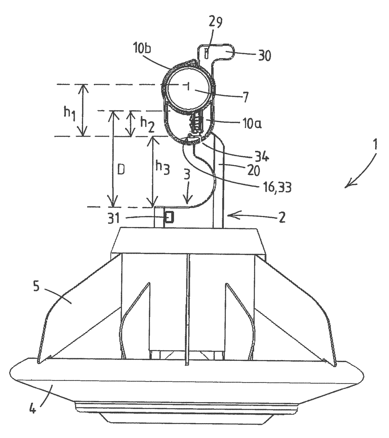
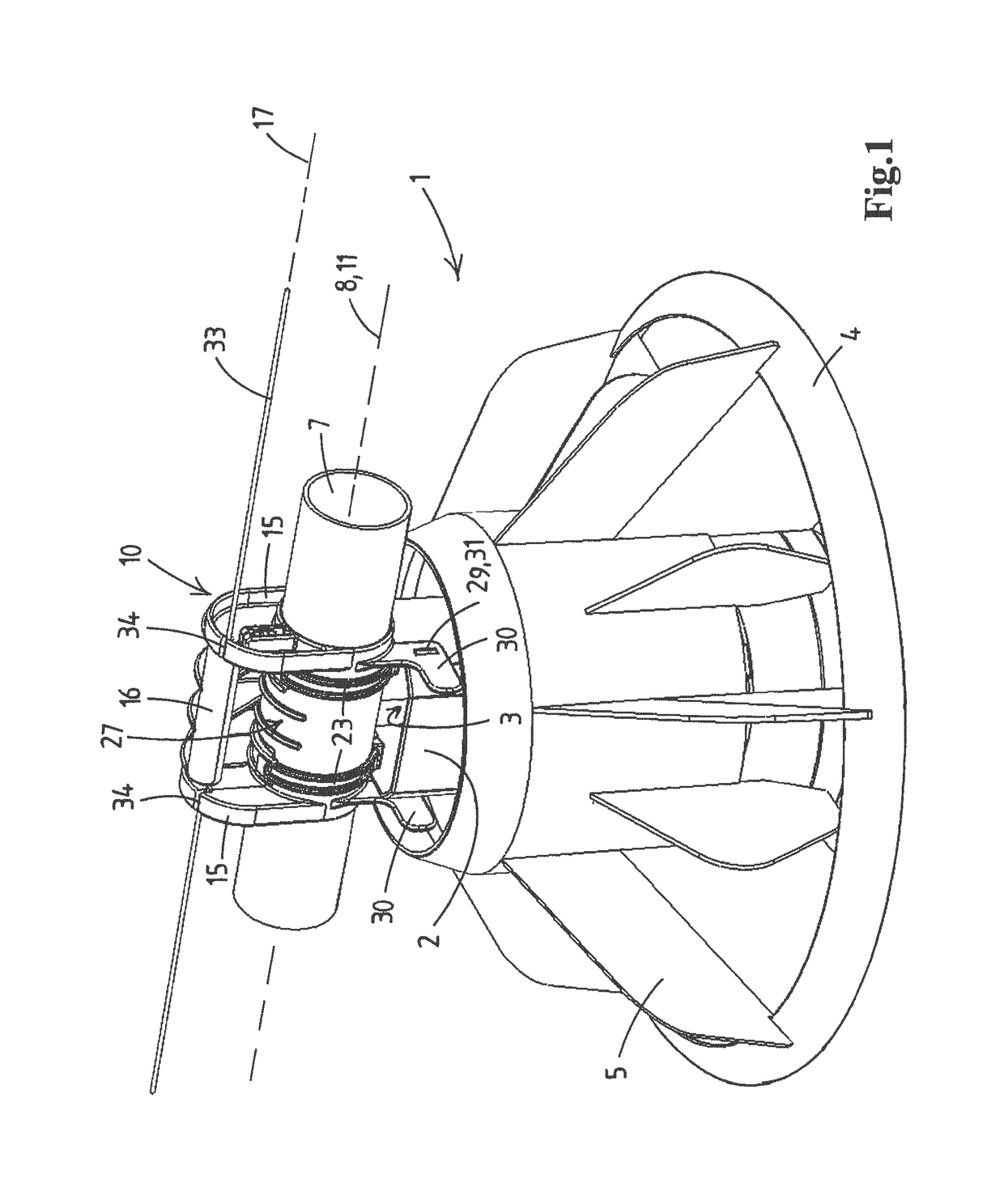
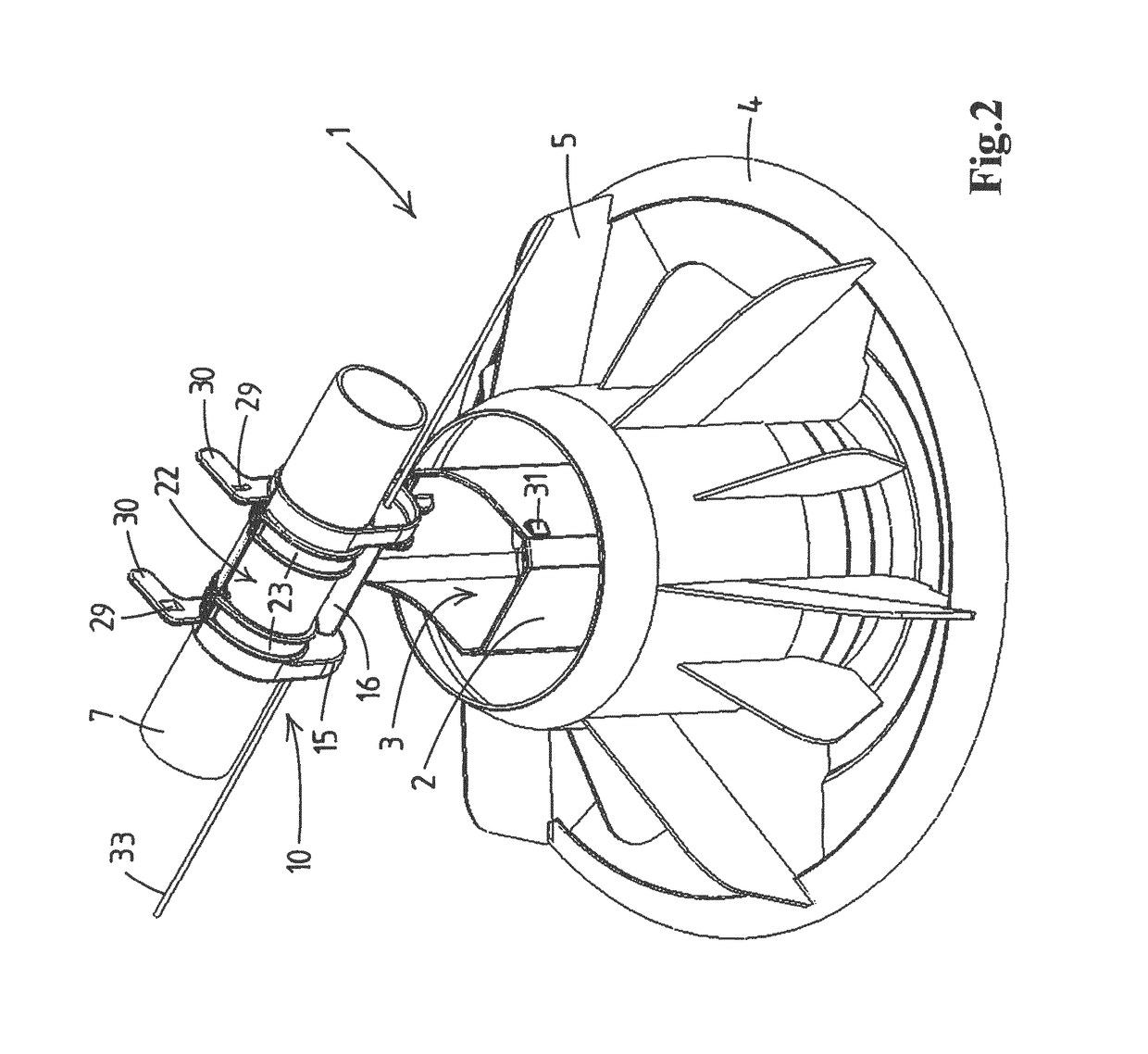
[0039]In FIGS. 1-8 only one feeding device of a feed distribution system is shown. This feeding device in its entirety has been given the reference numeral 1. The device 1 comprises a drop tube 2 having an inlet 3 at an upper end thereof. At a lower end the drop tube 2 opens out above a dispensing pan 4 connected to this drop tube 2. The drop tube 2 is equipped with radially extending partitions 5 dividing the dispensing pan in distinctive feeding sections.

[0040]In FIGS. 1-8 only a small segment of a conveyor pipe 7 is shown. This segment of the pipe 7 is positioned with its longitudinal axis 8 substantially horizontal and leads to a feed storage (not shown), like a silo, filled with feed for poultry, like broilers. Suitable transportation means (not shown) are provided, like a rotatable screw or disc chain scraper extending inside the pipe 7, for transporting the feed out of the storage via the conveyor pipe 7 towards the feeding device 1.

[0041]The segment of the pipe 7 is provided...


PUM


Abstract

A poultry feed distribution system includes a feed storage, a conveyor line and feeding devices. Each feeding device has an attachment part that is rotatable around the line. The attachment part has a drop tube of the device hingedly connected thereto. The attachment part together with the hinge connection to the drop tube is rotatable around the line between a feeding and a cleaning position, with an inlet of the drop tube getting distanced from the line when the attachment part together with the hinge connection to the drop tube is rotated from the feeding to the cleaning position.

Description

CROSS-REFERENCE TO RELATED APPLICATIONS[0001]This application is the National Stage of International Application No. PCT / EP2014 / 059298 filed May 7, 2014, which claims the benefit of Netherlands Application No. NL 2010765, filed May 7, 2013, the contents of which is incorporated by reference herein.FIELD OF THE INVENTION[0002]The invention relates to a feed distribution system for feeding poultry, such as chickens, turkeys, etc., in a poultry house.BACKGROUND OF THE INVENTION[0003]From the state of the art a large number of feed distribution systems are known. These systems have in common the fact that fixed feed dispensing points are present in the poultry house, and that the feed to be dispensed has to be conveyed from a central storage place to said feed dispensing points. For the conveyance of the feed a pipe conveyor system is present, which comprises one or more substantially horizontally directed feed conveyor pipes, which are disposed substantially parallel to each other, and...

Claims


Application Information

Patent Timeline
Patent Type & Authority Patents(United States)
IPC IPC(8): B08B3/02A01K39/012
CPCA01K39/0125B08B3/02A01K39/012
Inventor VAN KERREBROECK, BRECHT
Owner ROXELL
Why Eureka
Try Eureka