Delay anchor

a technology of delay anchor and anchor rod, which is applied in the field of posttension concrete construction, can solve the problems of splicing chuck, in-line stressing coupler, and unused portion of the tendon sitting out exposed,

Active Publication Date: 2019-08-27
SUNCOAST POST TENSION LTD
View PDF9 Cites 0 Cited by
  • Summary
  • Abstract
  • Description
  • Claims
  • Application Information

AI Technical Summary

Benefits of technology

[0014]It is, therefore, an object of the present invention to provide a delay anchor that allows a tendon from one phase of construction to be terminated at a joint adjoining the next phase of construction, protected there from the elements, and later coupled to a remaining portion of the tendon.
[0015]It is another object to provide a delay anchor that is economical to produce, simple to assemble in the field, not prone to corrosion or deterioration, and stronger and more robust than prior art devices.

Problems solved by technology

The first phase would be stressed, but in many cases this leaves the unused portion of the tendon sitting out exposed for months until the second phase (exterior ramp) can be poured.
The exposure to the elements can over time cause the tendon to corrode and lead to early failure.
Unfortunately, because of the use of threaded collars these prior art barrel couplers, splice chucks, or in-line stressing couplers are difficult to assemble in the field.
In addition, they are susceptible to failure and particularly susceptible of corrosion and deterioration.
The weakening of any component within the splice chuck can compromise the overall integrity of the splice chuck and, possibly, release the end of one tendon from the end of an adjoining tendon and compromise a joint in the concrete structure.

Method used


Image

  • Delay anchor
  • Delay anchor
  • Delay anchor

Examples


Embodiment Construction

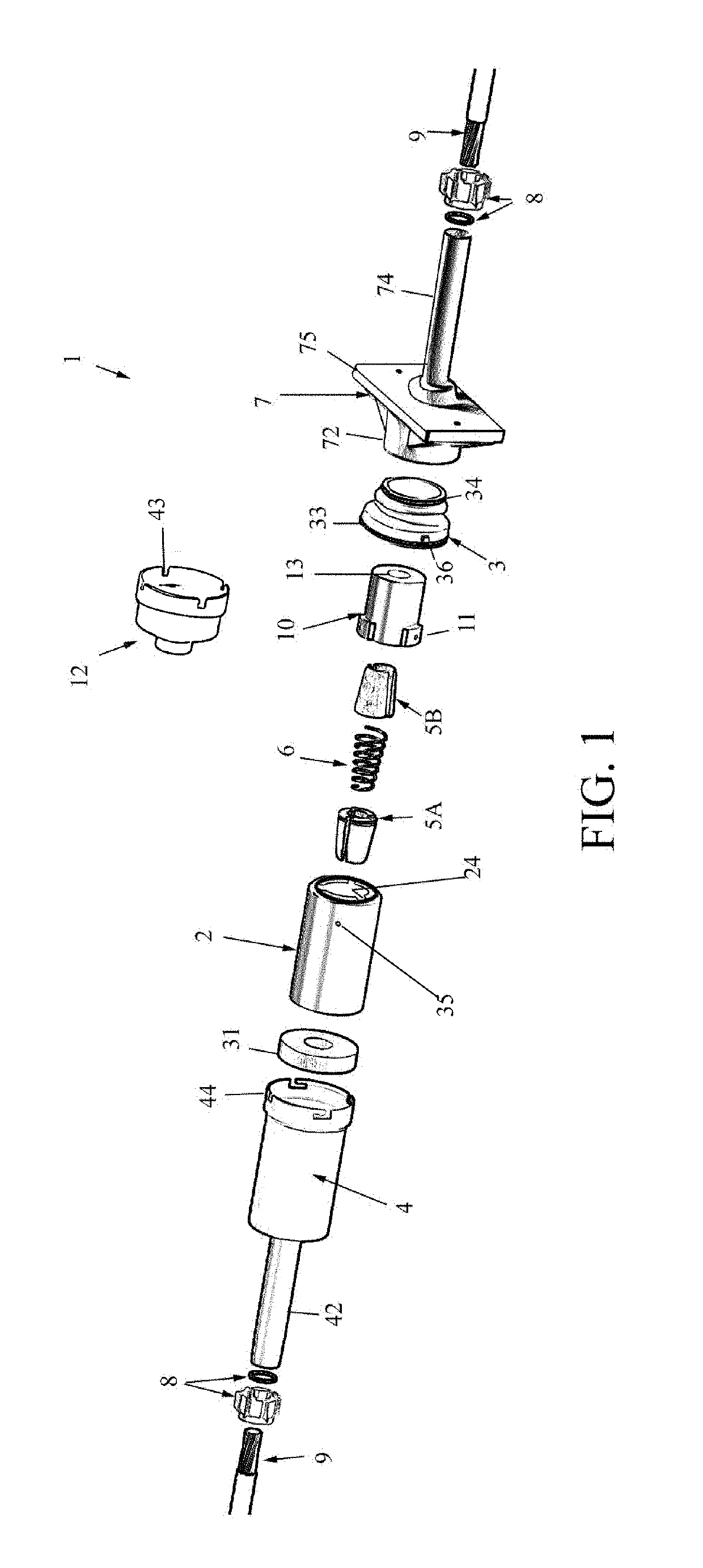
[0029]The present invention according to a preferred embodiment of the invention and as shown in FIG. 1 is a delay anchor 1 for anchoring terminal ends of a discontinuous tendon 9 at a concrete construction joint. The delay anchor 1 generally comprises a coupling sleeve 2 open at one (exposed) end, and partially closed at the other end except for a central through hole 22 (obscured in FIG. 1) conforming in size to pass the discontinuous end of sheathed tendon 9. The coupling sleeve 2 is internally configured with a frusto-conical recess 21 (to be described) tapering down to through-hole 22 for seating and compressing a first set of tendon wedges 5A inserted therein. The coupling sleeve 2 is also internally configured at its open mouth with a plurality of internal locking channels 24 that provide a twist-lock insertion feature for a stressing barrel 10. The stressing barrel 10 is an annular member sized for slidably receipt into the mouth of coupling sleeve 2, and formed with a corre...


PUM


Abstract

A delay anchor (delay anchor) for coupling terminal ends of two discontinuous tendons together resulting in a structurally continuous single tendon. The delay anchor generally comprises a coupling sleeve seating one set of tendon wedges for clamping one tendon end, and a stressing barrel seating a second set of tendon wedges for the other tendon end, the stressing barrel being attached to the coupling sleeve, and a compression spring biasing the two assemblies apart. The coupling sleeve is internally configured with a plurality of internal locking channels, and the stressing barrel has a plurality of radially protruding locking lugs slidable therein to provide a twist-lock insertion feature. An encapsulation insert is engaged to one side of an intermediate anchor and an encapsulation sleeve locks onto the encapsulation insert and covers and weather seals all internal components of the delay anchor.

Description

CROSS-REFERENCE TO RELATED APPLICATION(S)[0001]The present application derives priority from U.S. provisional application Ser. No. 62 / 483,754 filed Apr. 10, 2017.BACKGROUND OF THE INVENTION[0002]1. Field of the Invention[0003]The present invention relates to post-tension concrete construction and, more particularly, to a delay anchor usable anywhere along the length of a continuous tendon to stress a portion of that tendon and permitting the portion of the tendon to temporarily terminate between adjacent concrete pour phases without requiring the adjacent concrete pour phase to be complete, but subsequently allowing the coupling of different portions of the tendon in the later concrete pour to join the portions of the tendon together to make a structurally continuous tendon.[0004]2. Description of the Background[0005]Post-tensioning concrete entails the use of high-strength steel strand, “tendons,” that are embedded in concrete and tensioned after the concrete hardens. Using tendons...

Claims


Application Information

Patent Timeline
Patent Type & Authority Patents(United States)
IPC IPC(8): E04C5/12E04C5/16E04G21/12
Inventor BUTTS, BRIANPRICE, RUSSELL
Owner SUNCOAST POST TENSION LTD
Why Eureka
Try Eureka