Positive displacement reciprocating pump assembly for dispensing predeterminedly precise amounts of fluid during both the up and down strokes of the pump piston

a technology of pump piston and piston rod, which is applied in the direction of positive displacement liquid engine, pump components, liquid fuel engine components, etc., can solve the problems of insufficient strength or robustness of piston rods, inability to pump and dispense particular fluids consistently precise volumetric amounts, and cost of necessary maintenance procedures. , to achieve the effect of simple structure, strong and robust, and simple structur

Active Publication Date: 2020-10-13
HOWSEMAN JR WILLIAM E
View PDF45 Cites 0 Cited by
  • Summary
  • Abstract
  • Description
  • Claims
  • Application Information

AI Technical Summary

Benefits of technology

[0005]An overall objective of the present invention is to provide a new and improved positive displacement reciprocating pump assembly. Another overall objective of the present invention is to provide a new and improved positive displacement reciprocating pump assembly which is relatively simple in structure. A further overall objective of the present invention is to provide a new and improved positive displacement reciprocating pump assembly which is relatively simple in structure and which can pump and dispense precise amounts of fluid both during the UP and DOWN strokes of the pump piston rod assembly. A still further overall objective of the present invention is to provide a new and improved positive displacement reciprocating pump assembly which utilizes pump piston rods which are relatively large in diametrical extent relative to the amount of fluid dispensed during each UP and DOWN stroke of the pump piston such that the pump piston rods are strong and robust so as to be capable of withstanding very high pressures as well as thousands of fluid dispensing cycles.SUMMARY OF THE INVENTION

Problems solved by technology

While the pumps disclosed within the aforenoted prior art patent documents are certainly capable of pumping fluids as intended, such conventional prior art pumps are not in fact capable of pumping and dispensing particular fluids in consistently precise volumetric amounts.
In addition, the aforenoted conventional pumps comprise complex valving and fluid flow circuitry in order to achieve their pumping and dispensing functions.
Accordingly, the piston rods are not sufficiently strong or robust enough to withstand thousands of reciprocating movements which are characteristic of such reciprocating pump piston rods throughout their normal service life.
Therefore, the pump piston rods need to be replaced more frequently than desirable which is expensive not only in terms of the cost of each pump piston rod, but in addition, the cost of the necessary maintenance procedures and the loss of valuable production time due to the fact that a particular pump is off-line or suffering downtime while the maintenance procedures are being performed.

Method used


Image

  • Positive displacement reciprocating pump assembly for dispensing predeterminedly precise amounts of fluid during both the up and down strokes of the pump piston
  • Positive displacement reciprocating pump assembly for dispensing predeterminedly precise amounts of fluid during both the up and down strokes of the pump piston
  • Positive displacement reciprocating pump assembly for dispensing predeterminedly precise amounts of fluid during both the up and down strokes of the pump piston

Examples


first embodiment

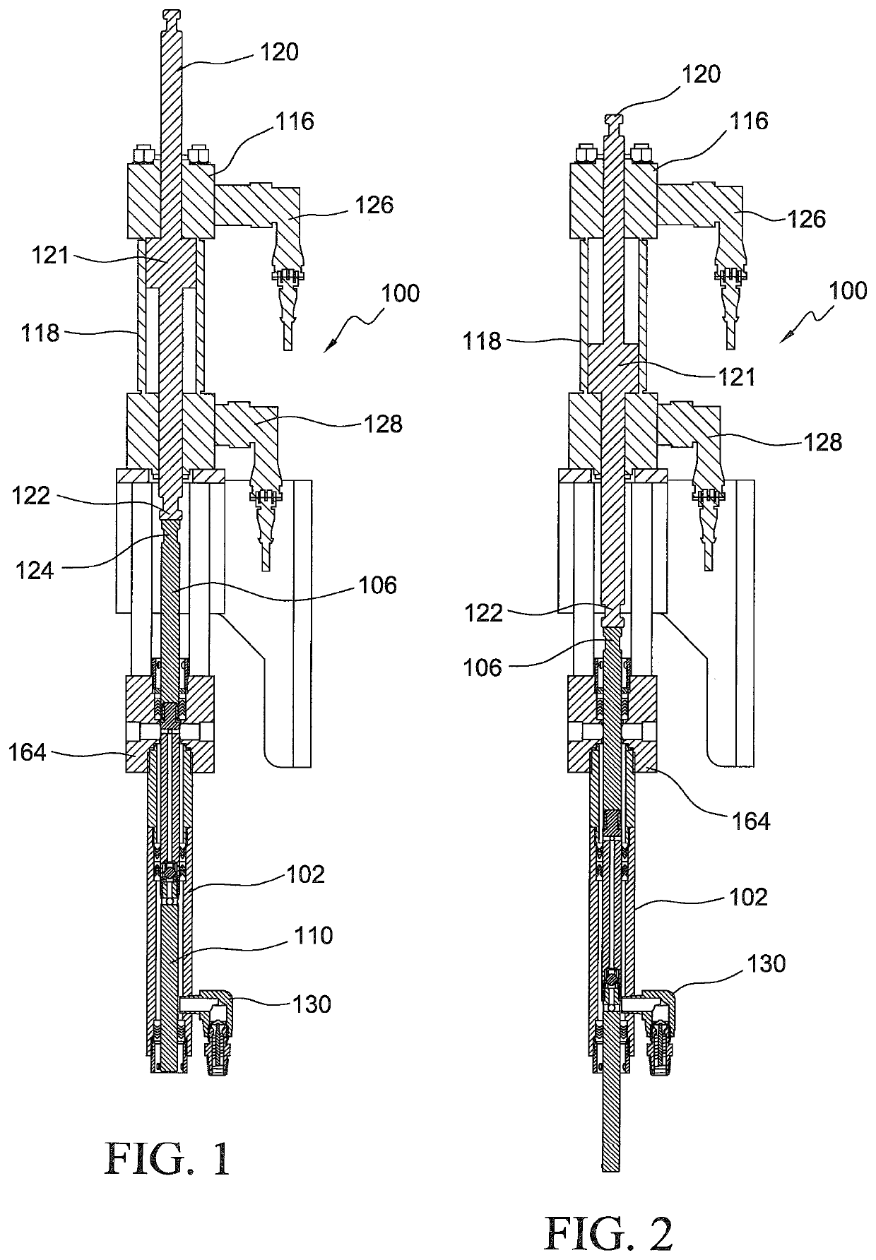
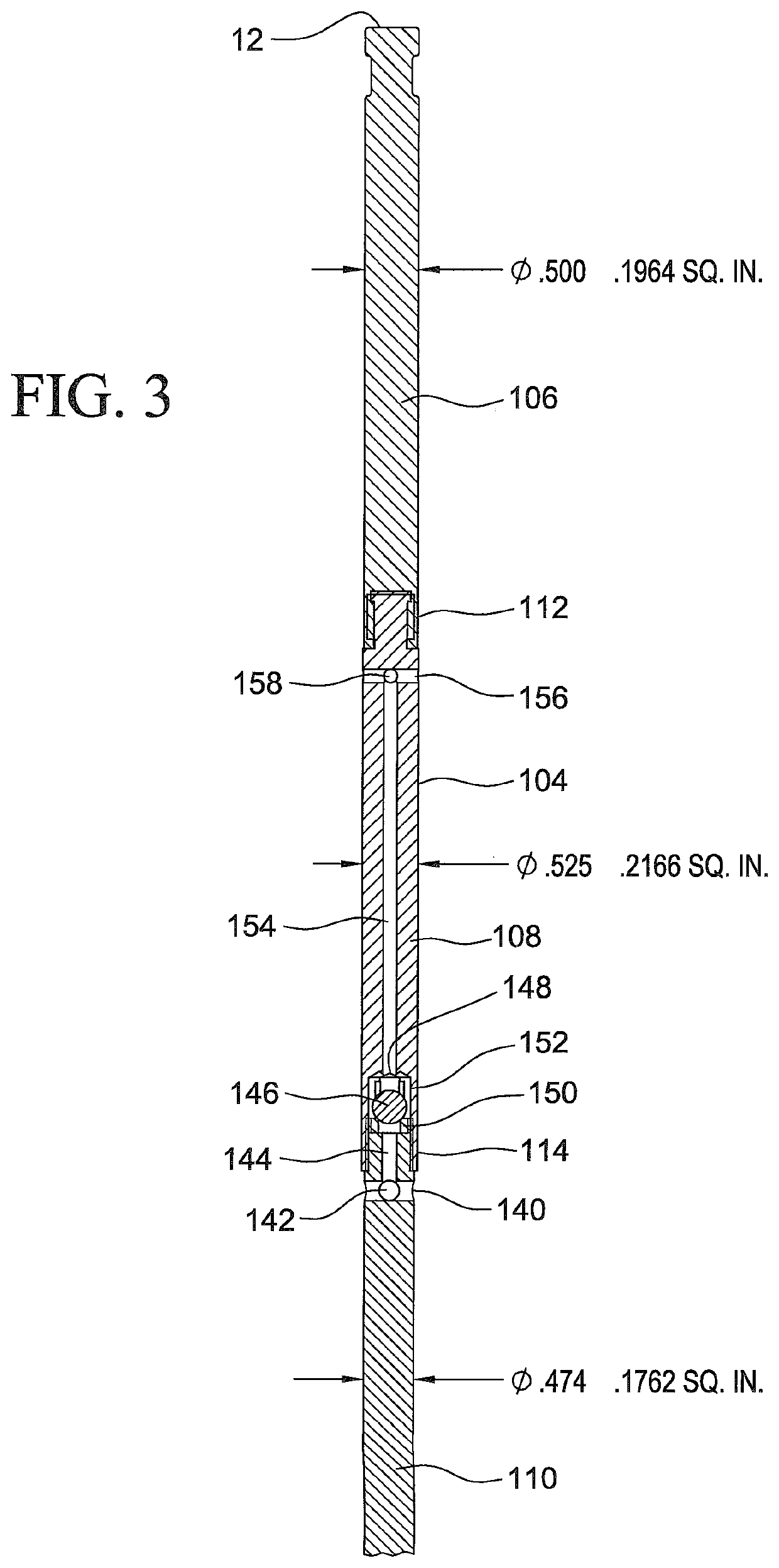
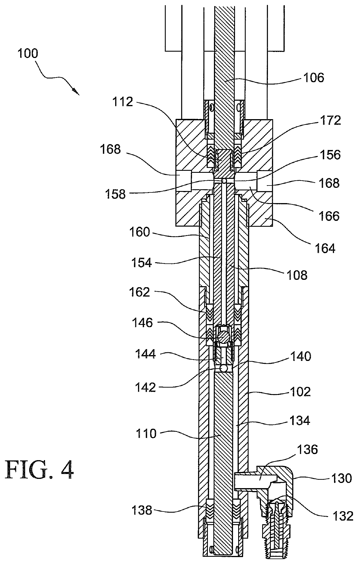
[0017]Referring now to the drawings, and more particularly to FIGS. 1-6 thereof, the description will first provide an overall general description of the new and improved positive displacement reciprocating pump assembly of the present invention, to be followed by a description of the operation of the pump assembly during both the UP and DOWN strokes of the working piston so as to clearly disclose the unique features of the new and improved pump assembly of the present invention in providing predeterminedly small but accurate amounts of fluid output. Accordingly, with reference to the noted drawings, it is initially seen that the new and improved reciprocating pump assembly of the present invention is generally indicated by the reference character 100. More particularly, it is seen that the new and improved reciprocating pump assembly 100 comprises a pump piston rod housing 102 within which the reciprocating pump piston rod assembly 104 is vertically movable between its raised or UP...

second embodiment

[0029]100—First embodiment of reciprocating pump assembly[0030]102—Pump piston rod housing[0031]104—Pump piston rod assembly[0032]106—First uppermost pump piston rod section of pump piston rod assembly[0033]108—Second intermediate pump piston rod section[0034]110—Third lowermost pump piston rod section of pump piston rod assembly[0035]112—Connection between first upper and second intermediate rod sections[0036]114—Connection between second and third piston rod sections[0037]116—Hydraulic drive motor assembly for pump piston rod assembly[0038]118—Housing of hydraulic drive motor assembly 116[0039]120—Actuator piston of hydraulic drive motor assembly 116[0040]121—Actuator piston head of hydraulic drive motor assembly 116[0041]122—Lower end portion of actuator piston 120[0042]124—Upper end portion of first uppermost pump piston rod section 106[0043]126—Input / output connector for hydraulic drive motor assembly 116[0044]128—Input / output connector for hydraulic drive motor assembly 116[00...


PUM


Abstract

The present invention comprises a new and improved positive displacement reciprocating pump wherein the pump comprises a pump rod assembly which comprises three different regions having three different external diameter dimensions or three different external diametrical extents wherein the first uppermost region is provided with an external diameter or diametrical extent of 0.500 inches which has a surface area of 0.1964 in2, the second intermediate one of the three regions is provided with an external diameter or diametrical extent of 0.525 inches which has a surface area of 0.2166 in2, and the third lowermost one of the three regions is provided with an external diameter or diametrical extent of 0.474 inches which has a surface area of 0.1762 in2. The differences between the external diameters or external diametrical extents of the three regions enable the positive displacement reciprocating pump to pump or dispense the same particular precise amount of fluid out from the pump during both the UP and DOWN strokes of the pump piston rod assembly. The piston rod assembly may comprise three piston rod sections or, alternatively, two piston rod sections and an intermediate rod seal or packing region movable along with the pump piston rod assembly.

Description

FIELD OF THE INVENTION[0001]The present invention relates generally to pumps, and more particularly to a new and improved positive displacement reciprocating pump assembly which is uniquely capable of dispensing a predeterminedly small precise amount of fluid during both the UP and DOWN strokes of the pump piston rod assembly.BACKGROUND OF THE INVENTION[0002]Reciprocating pumps are of course well known in the art for dispensing a variety of different fluids. Examples of known reciprocating dispensing pumps can be appreciated as a result of reference being made to U.S. Pat. No. 7,296,981 which issued to Strong on Nov. 20, 2007; U.S. Pat. No. 6,619,316 which issued to Wiechers et al. on Sep. 16, 2003; U.S. Pat. No. 6,558,141 which issued to Vonalt et al. on May 6, 2003; U.S. Pat. No. 5,984,646 which issued to Renfro et al. on Nov. 16, 1999; U.S. Pat. No. 5,671,656 which issued to Cyphers et al. on Sep. 30, 1997; U.S. Pat. No. 5,647,737 which issued to Gardner et al. on Jul. 15, 1997; ...

Claims


Application Information

Patent Timeline
Patent Type & Authority Patents(United States)
IPC IPC(8): F04B53/14F04B13/00F04B53/02F04B53/16
CPCF04B53/143F04B53/02F04B13/00F04B53/144F04B53/16
Inventor HOWSEMAN, JR., WILLIAM E.
Owner HOWSEMAN JR WILLIAM E
Why Eureka
Try Eureka