Asset tracking and work tool identification

Active Publication Date: 2018-04-10
CATERPILLAR INC
View PDF16 Cites 11 Cited by
  • Summary
  • Abstract
  • Description
  • Claims
  • Application Information

AI Technical Summary

Benefits of technology

This patent describes a tracking system for a work tool that can be used in a work area. The system includes a tracking device that identifies the work tool and a scanning device that can detect the work tool within the area. The system also has a location identification module that generates a work tool location signal with a unique identifier and a time stamp. A communication module adds the time stamp to the location signal and sends it to an asset location center. This allows the system to track the location of the work tool and display it on a database. The technical effect of this patent is the improved efficiency and accuracy of tracking work tools in a work area, which can improve work safety and efficiency.

Problems solved by technology

Furthermore, while the work tool may remain stationary when not in use, the work machine may continue to move about the job site, often times travelling from one end of the job site to the other.
Additionally, it may become increasingly difficult to keep track of where a work tool is located at a job site that has more than one work machine and a variety of different work tools.
Furthermore, when changing between work tools, different work tools may require the operator of the work machine to reconfigure or readjust operational parameters of the work machine such as hydraulic pressure and speed.
This may increase the amount of time it takes for an operator to locate the work tool that is needed and / or may increase the amount of time it takes to complete the task or operation.

Method used


Image

  • Asset tracking and work tool identification
  • Asset tracking and work tool identification
  • Asset tracking and work tool identification

Examples


Embodiment Construction

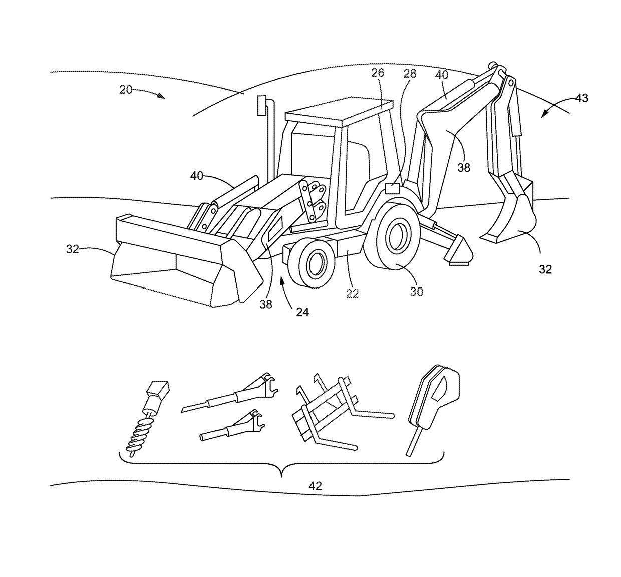
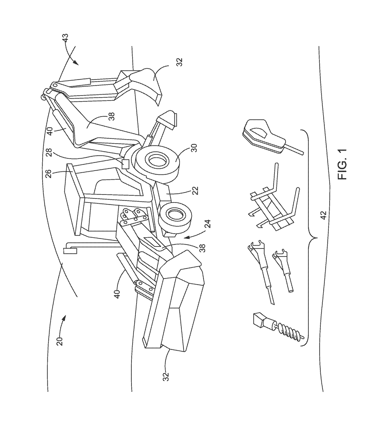
[0014]Referring now to the drawings and with specific reference to FIG. 1, a work machine 20 is shown, in accordance with certain embodiments of the present disclosure. While one non-limiting example of the work machine 20 is illustrated as a loader / backhoe, it will be understood that the work machine 20 may include other types of machines such as but not limited to, a skid steer, a dozer, a front-end loader, an excavator, a track-type machine, an on-road truck, an off-road truck, a motor grader, industrial mining equipment, and any other such machine. The work machine 20 may include a frame 22 configured to support a power source 24, and an operator compartment or operator cabin 26. In some embodiments, the power source 24 may be a power generating source such as but not limited to, a diesel combustion engine, a gasoline combustion engine, an electric motor, and any other known power generating source or combination thereof. Moreover, the operator compartment 26 may include a machi...


PUM


Abstract

A tracking system for a work tool is disclosed. The tracking system may include a tracking device coupled to the work tool and configured to transmit a work tool identification signal and a scanning device configured to scan and detect the work tool identification signal within the area around the scanning device and the tracking device. A location identification module and a communication module may be coupled to the scanning device and configured to receive the work tool identification signal, generate a work tool location signal including a location indicator and an identification of the work tool, add a date and time stamp to the work tool location signal and transmit the work tool location signal to an asset location center. The tracking system may further include a controller configured to receive and save the work tool location signal with the date and time stamp into an asset location database.

Description

FIELD OF THE DISCLOSURE[0001]The present disclosure relates generally to a tracking system and, more particularly, relates to a tracking system for monitoring and identifying work tools.BACKGROUND OF THE DISCLOSURE[0002]Work machines, such as backhoes, skid steers, dozers, front-end loaders, excavators, track type machines, on-road trucks, off-road trucks, motor graders, industrial mining equipment, and the like may be used in mining, construction, agriculture, petroleum, and other such applications. During operation, one or more work tools may be operably coupled to the work machine in order to complete a specific task or operation. Furthermore, the work tool may be interchangeably configured such that when one task is completed the current work tool may be detached and another work tool may be attached to the work machine to carry out a subsequent task. As a result, the work machine may use a variety of different work tools when performing different tasks or operations around a jo...

Claims


Application Information

Patent Timeline
IPC IPC(8): E02F9/26G06K7/10H04B1/3827E02F5/14E02F3/32
CPCE02F9/264G06K7/10386H04B1/3833E02F5/145E02F3/32G06K2007/10524G06Q10/0833E02F3/963G07C3/00
Inventor REED, JOSHUA D.BERGERHOUSE, BRADLEY F.
Owner CATERPILLAR INC
Why Eureka
Try Eureka