Lightning protection device for an antenna receiver, and aircraft comprising same

a protection device and antenna receiver technology, applied in the direction of overvoltage protection resistors, emergency protective arrangements for limiting excess voltage/current, and arrangements responsive to excess voltage, can solve the problems of significant standing-wave ratio, miniature surface mounted capacitors cannot tolerate high voltage levels, and the capacitance achieved with a discreet component can barely meet both

Active Publication Date: 2018-04-10
AIRBUS SAS
View PDF8 Cites 0 Cited by
  • Summary
  • Abstract
  • Description
  • Claims
  • Application Information

AI Technical Summary

Benefits of technology

[0007]The capacitor should have a level of impedance sufficiently low in the area of antenna frequency that it will not introduce an undesirable standing-wave ratio and that it should be able to tolerate voltage in excess of 1 KV.

Problems solved by technology

Capacitance achieved with a discreet component can hardly meet both of these requirements simultaneously, because the components that can tolerate these voltage levels are frequently voluminous and have strongly inductive behavior with these frequencies, which would result in a significant standing-wave ratio.
In the same way, a miniature surface mounted capacitor cannot tolerate high voltage levels because of its low inductive behavior.
These values will result in the introduction of an undesirable standing wave.

Method used


Image

  • Lightning protection device for an antenna receiver, and aircraft comprising same
  • Lightning protection device for an antenna receiver, and aircraft comprising same
  • Lightning protection device for an antenna receiver, and aircraft comprising same

Examples


Embodiment Construction

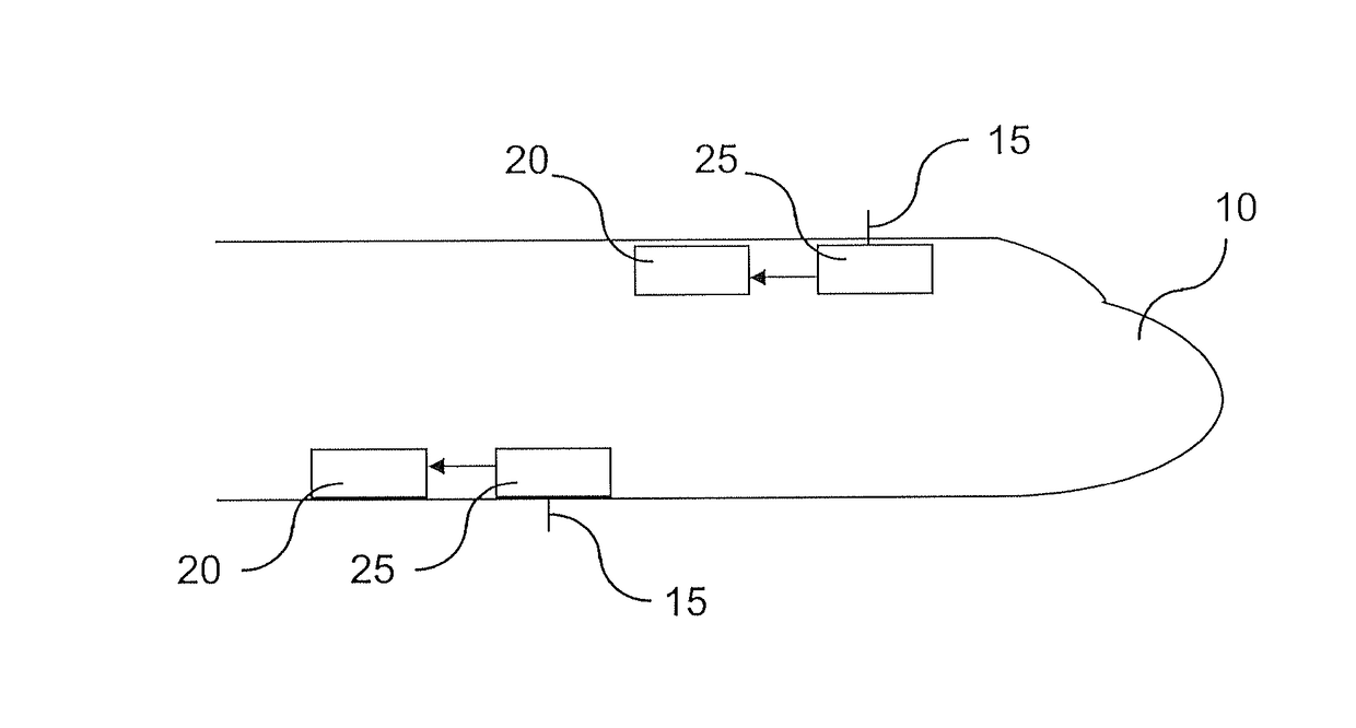
[0025]In FIG. 1, we observe an aircraft 10 containing antennas 15, antenna receivers 20 and lightning protection devices 25.

[0026]The aircraft 10 is of no particular type, it may be civilian or military, with or without pilots. In the preferred embodiments, the aircraft 10 has a fuselage comprising electrically insulating materials, notably composite materials. The antennas 15 are of a known type. Because of their shape and their position, they are particularly susceptible to lightning. The antenna receivers 20 or of a known type. They are connected to avionics and / or communications equipment, which is not shown. Each lightning protective device 25 is electrically inserted between an antenna 15 and an antenna receiver 20. A particular embodiment of a lightning protection device 25 is illustrated in FIG. 2.

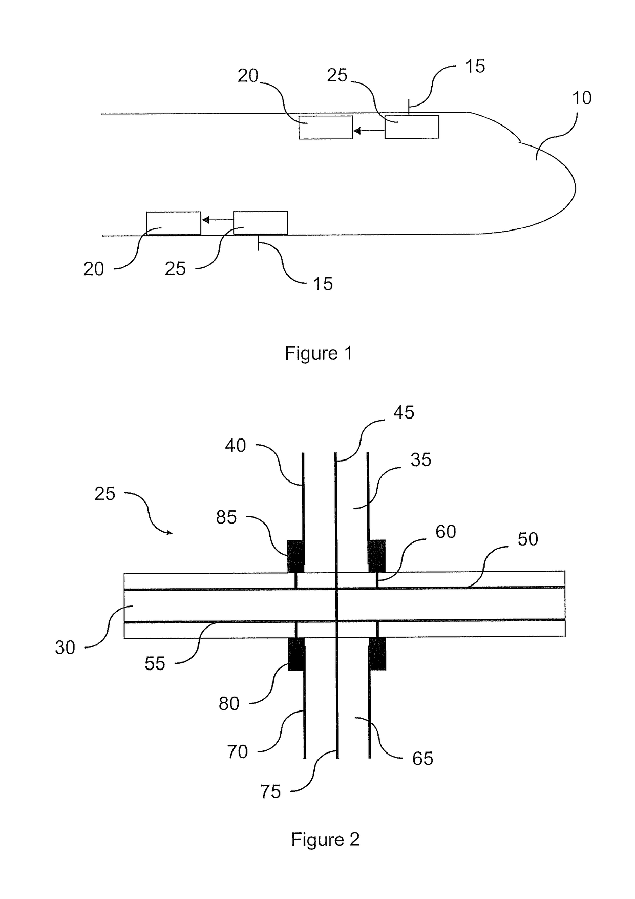
[0027]In the particular embodiment shown in FIG. 2, the lightning protection device 25 is based on a printed circuit board, or PCB, which is the acronym for “Printed Circuit Board”...


PUM


Abstract

A lightning protection device for an antenna receiver includes a shield for a coaxial cable connected to the antenna, and a high-pass filter mounted in series relative to the shield and capable of limiting the low-frequency power flowing in the coaxial cable, including a capacitor and an inductor lower than 1 ohm at the lowest frequency used by the receiver, the capacitor including at least one layer of a conductive material embedded in a printed circuit. The capacitor may be made of a printed circuit including at least two floor plans, each of which is connected to the ground of a connector of the coaxial cable. The printed circuit may include at least one layer of a highly pervious material sandwiched between two layers of a conductive material.

Description

BACKGROUND OF THE INVENTION[0001]This invention relates to a lighting protection device for an antenna receiver in an aircraft and aircraft comprising same. This invention applies particularly to airplanes of which the fuselage contains electrically insulating materials, in particular composite materials.[0002]Numerous antennas are installed on the fuselage of an aircraft. However, the widespread use of composite materials in the design of fuselages gives rise to numerous difficulties with relation to electrical conduction. In particular, significant contact resistance is present between the metallic bases of an antenna which is fixed to a fuselage and the composite panel onto which this base is fixed. The order of magnitude of this resistance is in the tens of Mega-Ohms. This high level of resistance causes current to circulate on the coaxial cable connected to the antenna when lightning strikes, on the order of 15 KA for a lightning strike of 200 KA, which is too restrictive for t...

Claims


Application Information

Patent Timeline
Patent Type & Authority Patents(United States)
IPC IPC(8): H01Q1/50
CPCH01Q1/50
Inventor MEYER, MARC
Owner AIRBUS SAS
Why Eureka
Try Eureka