Discharge device

a discharge device and discharge technology, applied in the direction of corona discharge, spark gap circuit, electrical equipment, etc., can solve the problems of ignitability and combustibility reduction, drive circuit breakage, environmental conservation and fuel depletion, etc., to prevent and suppress the occurrence of secondary disasters

Inactive Publication Date: 2018-04-10
MITSUBISHI ELECTRIC CORP
View PDF7 Cites 4 Cited by
  • Summary
  • Abstract
  • Description
  • Claims
  • Application Information

AI Technical Summary

Benefits of technology

[0009]The present invention has been made for solving the above problems and an object thereof is to protect apparatuses included in a discharge device from damage and to prevent and suppress the occurrence of a secondary disaster in the case where an output path of AC power to be supplied from the discharge device to a discharge load is disconnected or becomes in a state of connection failure.
[0011]As the discharge device according to the present invention has a function of accurately determining the disconnection in the output path of the AC power to be supplied from the discharge device to the discharge load or occurrence of a malfunction causing a connection failure, therefore, advantages that apparatuses included in the discharge device are protected from damage by stopping the operation of the discharge device when the malfunction occurs and the occurrence of secondary disasters can be prevented and suppressed can be expected.

Problems solved by technology

In recent years, problems of environmental conservation and fuel depletion are raised, and it is urgently necessary to take measures against these problems also in the automotive industry.
However, the burnt gas as the exhaust gas is non-combustible and has a high heat capacity with respect to the air, therefore, there is a problem that ignitibility and combustibility are reduced when a large quantity of burnt gas is taken by the EGR.
In the case where a prescribed amount of current or more flows through the path, the operational amplifier, the switch or the like on the path may be damaged and the drive circuit may be broken, however, there is a case that an abnormality is not found just by observing a signal of the current sensor 46 as the drive circuit is operated in a near normal state.

Method used


Image

  • Discharge device
  • Discharge device
  • Discharge device

Examples


embodiment 1

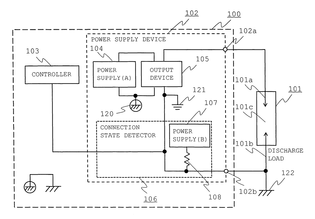
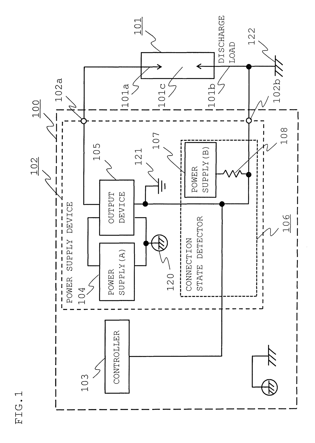
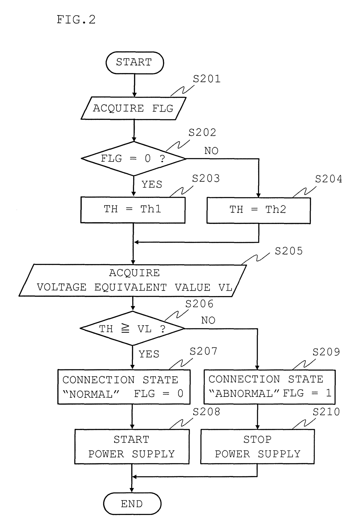
[0020]FIG. 1 is a circuit block diagram showing an outline of a structure of a discharge device according to Embodiment 1, FIG. 2 is a flowchart showing an operation procedure of a controller of the discharge device and FIG. 3 is a circuit diagram showing the details of the structure of an example of the discharge device. FIG. 4 A to FIG. 4D are operation timing charts of the controller of the example.

[0021]As shown in FIG. 1, a discharge device 100 includes a power supply device 102 supplying AC power for generating the discharge in a clearance 101c to a discharge load 101 having a high voltage electrode 101a and a grounding electrode 101b arranged to face the high voltage electrode 101a with the clearance 101c and connected to a ground GND 122 and a controller 103 controlling the power supply device 102

[0022]Here, the power supply device 101 includes a power supply (A) 104 using an internal GND (1) 120 as a reference, an output device 105 outputting AC power to be supplied to the ...

embodiment 2

[0066]FIG. 5 is a circuit diagram showing the details of a structure of a discharge device according to Embodiment 2, and FIG. 6A and FIG. 6B show operation timing charts of a controller of the discharge device. The power supply (B) 107 for detecting the connection state corresponds to the DC power supply (2) 306 in the example of Embodiment 1, however, the structure differs from the structure of the discharge device according to Embodiment 1 in a point that the power supply (B) 107 is changed to an AC power supply 506 in a discharge device 200 according to Embodiment 2. Furthermore, a switching device 508 for controlling the AC power supply 506 is added. As other components are the same as those of Embodiment 1, explanation thereof is omitted.

[0067]The connection point (L) 311 is assumed to be completely disconnected in Embodiment 1, however, there exists a state in which the connection is incompletely made, namely, an almost disconnected state, which is not the complete disconnect...


PUM


Abstract

A discharge device includes a power supply device supplying AC power for generating a discharge in a clearance to a discharge load having a high-voltage electrode and a grounding electrode arranged to face the high-voltage electrode with the clearance and connected to a ground GND and having a connection state detector detecting a connection state of an output path of AC power, and a controller controlling the power supply device by determining the existence of an abnormality in the connection state and deciding whether AC power can be supplied or not. In the case where a disconnection or a connection failure occurs in the output path of AC power to be supplied from the discharge device to the discharge load, apparatuses included in the discharge device are protected from damage as well as occurrence of a secondary disaster can be prevented and suppressed.

Description

BACKGROUND OF THE INVENTION[0001]Field of the Invention[0002]The present invention relates to a discharge device using discharge mainly by AC power which is used for, for example, fuel ignition in an internal-combustion engine.[0003]Description of the Related Art[0004]In recent years, problems of environmental conservation and fuel depletion are raised, and it is urgently necessary to take measures against these problems also in the automotive industry. As an example of these measures, there is a method of dramatically improving fuel consumption by reducing pumping loss (intake and exhaust loss) using EGR (Exhaust Gas Recirculation). However, the burnt gas as the exhaust gas is non-combustible and has a high heat capacity with respect to the air, therefore, there is a problem that ignitibility and combustibility are reduced when a large quantity of burnt gas is taken by the EGR.[0005]As one of solutions for the problem, for example, in a corona discharge ignition system in JP-2014-5...

Claims


Application Information

Patent Timeline
Patent Type & Authority Patents(United States)
IPC IPC(8): H01T19/00
CPCH01T19/00H01T15/00
Inventor TANAYA, KIMIHIKO
Owner MITSUBISHI ELECTRIC CORP
Why Eureka
Try Eureka