
Radioimaging using low dose isotope

a radio-isotope and low-dose technology, applied in the field of nuclear imaging, can solve the problems of not providing spectral information for pet imaging, not distinguishing between radio-isotopes, etc., and achieve the effects of preventing saturation, movability of detecting units, and unprecedented sensitivity

Active Publication Date: 2018-04-17
SPECTRUM DYNAMICS MEDICAL LTD
View PDF469 Cites 2 Cited by
  • Summary
  • Abstract
  • Description
  • Claims
  • Application Information

AI Technical Summary

Benefits of technology

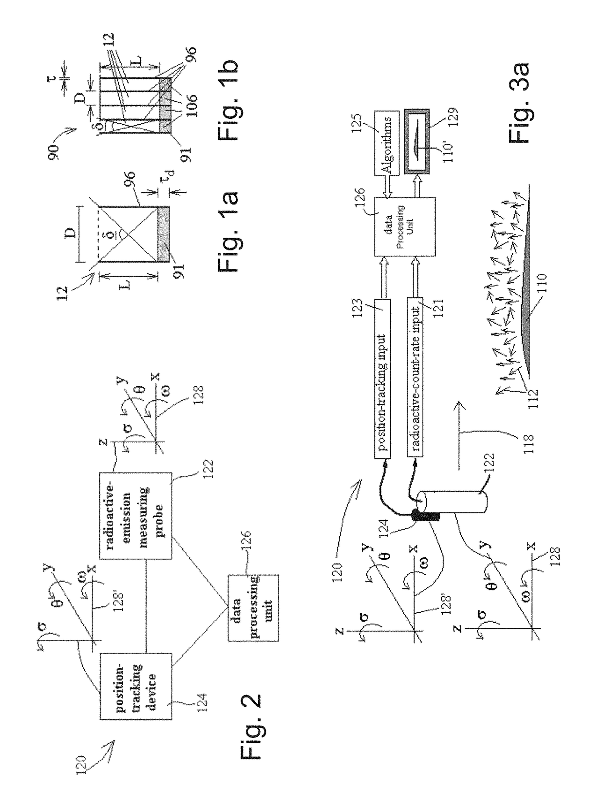
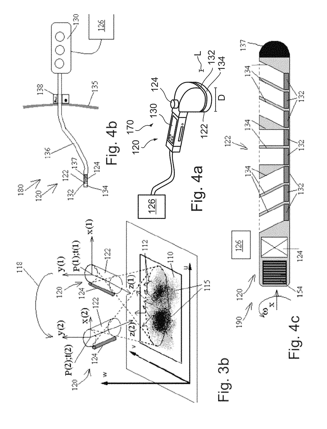
[0024]The present invention emerges from the development of a radioimaging camera characterized by unprecedented sensitivity. The sensitivity of the camera is attributed, as is further detailed hereiunder, to at least the following constructual features: (a) a plurality of detecting units; (b) movability of the detecting units one with respect to the other; (c) thus allowing concetrated focus on a region-of-interest by the individual detecting units; and (d) weiring diagaram with minimal multiplexing, thereby preventing saturation thereof.
[0025]As a result of this sensitivity, it is now possible using the camera of the present invention to (a) detect low dose radiopharmaceuticals; (b) perform fast kinetic studies; (c) extract kinetic parameters for the distribution of a radiopharmaceutical under different diagnostic setups, thereby allowing (i) formulating radiopharmaceuticals based on the newly achieved knowledge of the kinetic patrameters; (ii) diagnostics based on the kinetic parameters; (iii) formulating new therapeutic drugs based on the kinetic parameters; and (iv) using the kinetic parameters as an input to the expert system for diagnostics; (d) provide images of co-administerred radipharmaceuticals; and (e) allow dianogstically meaningfull imaging at a far faster rate as compared to conventional prior art radioimaging cameras.
[0035]In a further possible embodiment of the present invention the width of each detector is about 10 cm wide, thus enabling regions of interest of even bigger diameters at said resolution and sensitivity with a smaller detector motion such that bigger objects are continuously viewed by the detector with only small angular detector motion.
[0039]It will be recognized by a person skilled in the art that a system built around the principles as described by the examples and embodiments of the present invention can thus reach the sensitivity necessary to detect substantially more than one photon from every 100 emitted. This result for an imaging system provides more than 100 time better sensitivity than commercially available cameras that have a sensitivity ranging from substantially from 170 counts / microCurie / minute (or 1 photon in 8500 photons emitted for a Low resolution low energy collimator to about 1 photon in every 15000 emitted for a high resolution medium energy collimator), while maintaining similar energy windows, and potentially similar or better resolution.

Problems solved by technology

Yet, since the annihilation gamma is of 0.511 Mev, regardless of the radio-isotope, PET imaging does not provide spectral information, and does not differentiate between radio-isotopes.

Method used


Image

  • Radioimaging using low dose isotope
  • Radioimaging using low dose isotope
  • Radioimaging using low dose isotope

Examples


example 1

[0394]Referring further to the drawings, FIGS. 18A and 18B schematically illustrate the radioactive-emission camera 10, of the single detecting unit 12 (see FIGS. 1A and 17A). The single detecting unit 12 has a motion with respect to the overall structure 20, which is a combination of a rotational motion around the x-axis, in the direction of ω, denoted by an arrow 44, and a translational motion along the x-axis, denoted by an arrow 46.

[0395]As a consequence, a spiral trace 48 is formed, for example, on an inner surface of a body lumen 232, as seen in FIG. 18B.

[0396]Preferably, the motions of the detecting unit 12 are contained within the overall structure 20, so that the external surface of the camera 10 remains stationary. The external surface of the camera may be formed of a carbon fiber, a plastic, or another material, which is substantially transparent to nuclear radiation.

example 2

[0397]Referring further to the drawings, FIGS. 18C and 18D schematically illustrate the radioactive-emission camera 10, of the single block 90 (FIGS. 1B and 17E). Note that all the detecting units 12 of the single block 90 move as a single body. The single block 90 has a motion with respect to the overall structure 20, which is a combination of the rotational motion around the x-axis, in the direction of ω, denoted by the arrow 44, and the translational motion along the x-axis, denoted by the arrow 46.

[0398]As a consequence, a plurality of spiral traces 49 is formed, for example, on an inner surface of a body lumen, as seen in FIG. 18D.

[0399]Preferably, the motions of the block 90 are contained within the overall structure 20, so that the external surface of the camera 10 remains stationary, wherein the external surface of the camera is substantially transparent to nuclear radiation.

example 3

[0400]Referring further to the drawings, FIGS. 19A-19E schematically illustrate the radioactive-emission camera 10, of the single block 90 of a plurality of the detecting units 12.

[0401]For understanding the motion of the camera 10 of the present example, it is desirable to define a cylindrical coordinate system of a longitudinal axis, x, and a radius r, wherein the motion around the longitudinal axis, x, is denoted by ω, while the motion around the radius r is denoted by φ.

[0402]The single block 90 has a motion with respect to the overall structure 20, which is performed in steps, as follows:

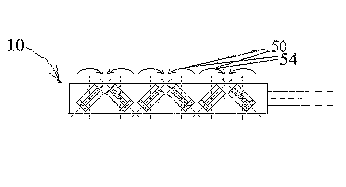
[0403]i. the windshield-wiper like oscillatory motion, around the radius r, in the direction of ±φ, as denoted by the arrow 50;

[0404]ii. the translational motion along the x-axis, by an amount Δx, to a new measuring position, as denoted by the arrow 46;

[0405]iii. after traversing the length of the camera, a rotational motion around the x-axis, in the direction of ω, by an amount Δω, as denoted ...


PUM

PropertyMeasurementUnit
solid angleaaaaaaaaaa
sizeaaaaaaaaaa
radioactive imagingaaaaaaaaaa

Abstract

Radioimaging methods, devices and radiopharmaceuticals therefor.

Description

RELATED APPLICATIONS[0001]This application is a continuation of U.S. patent application Ser. No. 11 / 980,653 filed on Oct. 31, 2007, which is a continuation of U.S. patent application Ser. No. 11 / 798,017 filed on May 9, 2007, now U.S. Pat. No. 8,586,932, which is a continuation-in-part of PCT Patent Application No. PCT / IL2005 / 001173 filed on Nov. 9, 2005, which is a continuation-in-part of both PCT Patent Application Nos. PCT / IL2005 / 000572 and PCT / IL2005 / 000575 both filed on Jun. 1, 2005.[0002]PCT Patent Application Nos. PCT / IL2005 / 000572 and PCT / IL2005 / 000575 claim the benefit of priority of U.S. Provisional Patent Application Nos. 60 / 648,690 filed on Feb. 2, 2005; 60 / 648,385 filed on Feb. 1, 2005; 60 / 640,215 filed on Jan. 3, 2005; 60 / 636,088 filed on Dec. 16, 2004; 60 / 635,630 filed on Dec. 14, 2004; 60 / 632,515 filed on Dec. 3, 2004; 60 / 632,236 filed on Dec. 2, 2004; 60 / 630,561 filed on Nov. 26, 2004 and 60 / 625,971 filed on Nov. 9, 2004.[0003]PCT Patent Application No. PCT / IL2005 / 00...

Claims


Application Information

Patent Timeline
Patent Type & Authority Patents(United States)
IPC IPC(8): A61B6/03A61K51/10A61K51/04A61K51/00A61B6/00A61B8/08A61B6/04
CPCA61B6/44A61B6/037A61B6/425A61B6/4258A61B6/4266A61B6/547A61K51/0478A61K51/1048A61K51/00A61B8/0825A61B6/0414A61B6/4275A61B8/0808A61B5/7285A61B6/4291A61B6/488A61B6/501A61B6/502A61B6/507A61B6/541A61B6/548A61B6/583A61B8/12A61B8/4416A61B8/543A61B5/06A61B5/415A61B5/416A61B5/418G01R33/481G01T1/1615G01T1/1642G01T1/2985
Inventor ROUSSO, BENNYBEN-HAIM, SHLOMORAVHON, RANZILBERSTEIN, YOELDICHTERMAN, ELIBEN-HAIM, SIMONAROTH, NATHANIEL
Owner SPECTRUM DYNAMICS MEDICAL LTD
Learn More