Electron spectroscopy system

a technology of electron spectroscopy and system, applied in the field of electron spectroscopy, can solve the problems of exacerbated traditional shortcomings in resolving these processes, difficult to obtain information, and inability to successfully develop advanced predictive models, so as to improve the time and energy resolution of the microscope and the detail of the image created. , to achieve the effect of improving the resolution of time and energy and improving the quality of the imag

Active Publication Date: 2019-03-28
BOARD OF TRUSTEES OPERATING MICHIGAN STATE UNIV
View PDF6 Cites 5 Cited by
  • Summary
  • Abstract
  • Description
  • Claims
  • Application Information

AI Technical Summary

Benefits of technology

[0011]A further aspect of the present electron spectroscopy system employs adaptive and / or adjustable optics to optimize both time and energy compression. Another aspect provides at least two RF lenses or cavities, one before a specimen and one after the specimen. Still another aspect includes a programmable controller and associated software instructions which automatically optimize and / or adjust multiple lens in a laser based electron microscope while images are being produced for a specimen. These aspects of the present system improve both the time and energy resolution of the microscope and the detail of the image created therewith. Additional advantages and features can be found in the following description and appended drawings.

Problems solved by technology

It is widely recognized that a major bottleneck to progress is the scarcity of experimental data on the local properties, which has prevented the successful development and validation of advanced predictive models.
However, such information is usually very difficult to obtain as it often involves multiple steps and collective modes that are frequently not accessible via optical devices.
The traditional shortcomings in resolving these processes are exacerbated by the limitations in terms of temporal resolution and sensitivity using only a single or very few electrons in each electron gun pulse or shot with conventional electron microscopes.
While advances in ultrafast imaging technology are now at the level where these spatiotemproal pattern may be imaged using ultrashort coherent X-ray beams or with coherent electron beams on the ultrafast timescale, the still existing challenge is to correlate these spatiotemporal patterns with their underlying electronic structure evolution that is the primary source of their functionalities.
However, the most advanced laser-based femtosecond (“fs”) angle-resolved spectroscopy for imaging band structures, namely ultrafast angle-resolved electron spectroscopy, is limited by its use of low energy electrons to two dimensional (“2D”) Fermi surfaces and Brillouin zones.
Meanwhile, a major challenge in this field is now reconciling the emerging properties due to macroscopic entanglement between different electronic orderings since such transformations not only depend on the properties of 2D electronic distributions, but also the interaction of the density waves through structures across the layers.
The most challenging issue thus far preventing wide-ranging applications of ultrafast EELS is the presence of space-charge effect resulting in poor time and energy resolutions in TEM.
Not only is the cross-section in core losses much lower, many applications involving chemical transformations and bonding changes are also typically less reproducible, thereby demanding orders of magnitude improvements in the instantaneous dose.
Such capabilities are currently not available in conventional electron-based spectroscopy systems.

Method used


Image

  • Electron spectroscopy system
  • Electron spectroscopy system
  • Electron spectroscopy system

Examples


first embodiment

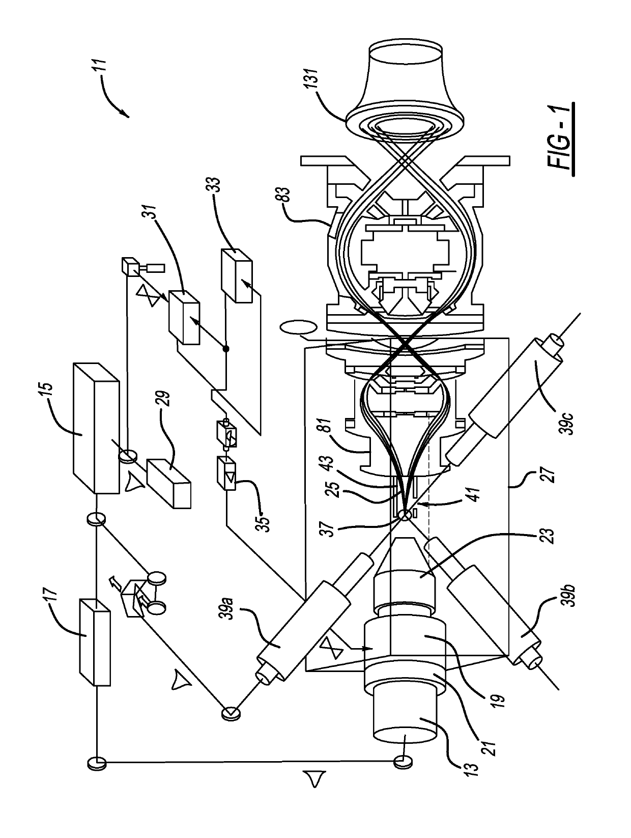
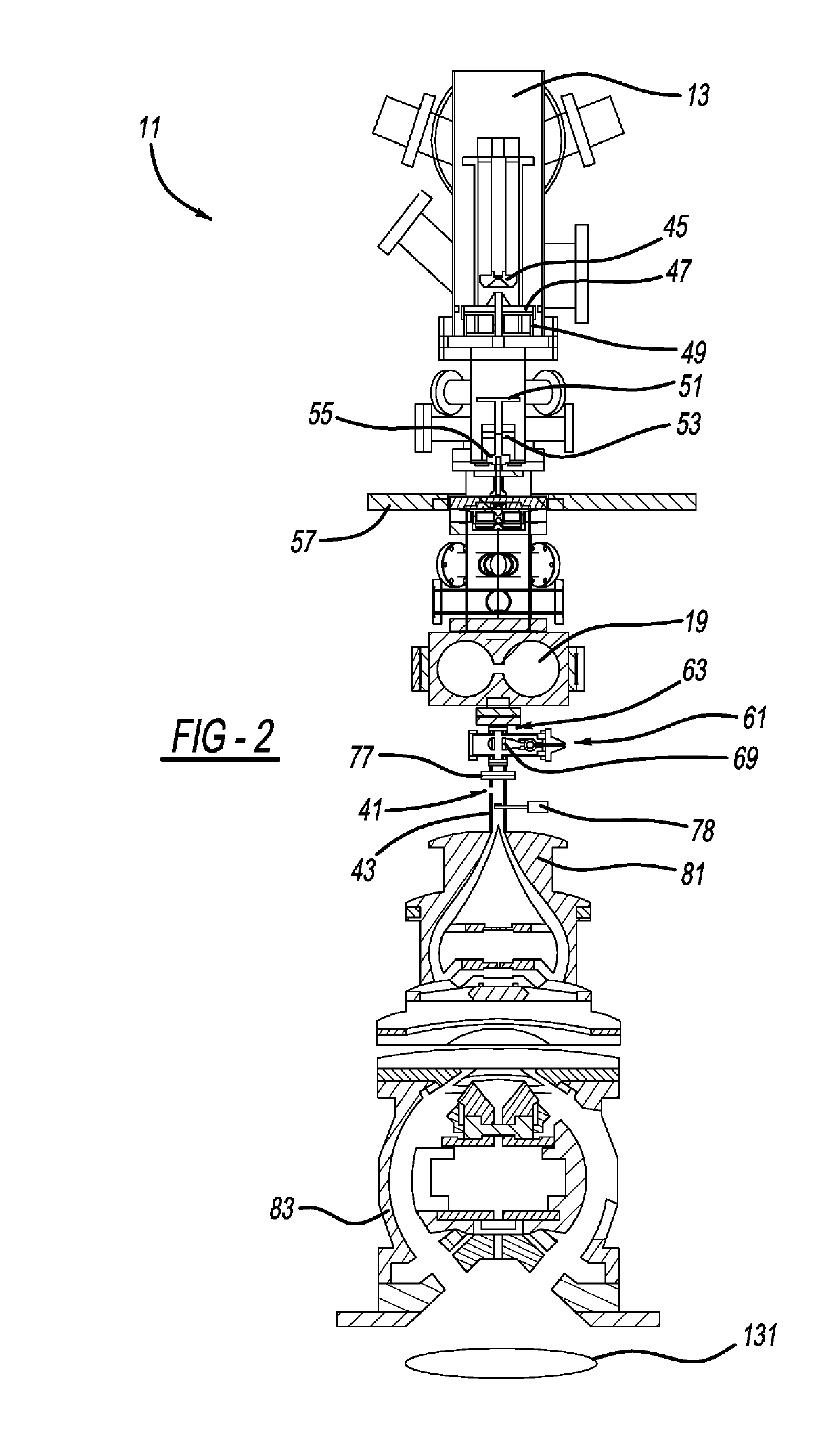
[0026]an electron spectroscopy system 11 is shown in FIGS. 1 and 2. System 11 includes a femtosecond photoelectron gun 13, which is driven by a fs laser 15 and harmonic generator pulse shaper 17 for high-brightness beam generation. System 11 further includes an energy-compression radio frequency (“RF”) cavity 19. RF cavity 19 is coupled to gun 13 through mode-matching optics 21 and an energy filter 23 to produce and emit monochromatic electron beams 25, containing a bunch of electrons in each pulse or shot, for the spectroscopy process in a vacuum chamber 27.

[0027]System 11 also includes a seed fs oscillator 29, a phase-lock loop 31, a master RF clock 33 and an RF amplifier 35. Laser pulses of 1 ps or less are preferred for sending to gun 13 and also to a specimen or sample 37. Even more preferable, 100 fs or less duration laser pulses are employed. The laser pulses are emitted from any one or more of time-resolved optical pumping members 39a, 39b and / or 39c, members 39b and 39c bei...

second embodiment

[0047]the present electron spectroscopy system 201 is disclosed in FIGS. 6-13. System 201 includes adaptive electron-optics in an electron microscope 203 aiming to boost a signal-to-noise ratio (“S / N”) while maintaining high energy and time resolutions in a few-electron pulse UEM system. A pair of longitudinal electron lenses or RF cavities 19 and 207 control the pulsed electron beams, resulting in favorable phase space evolution to improve resolutions and overcome space-charge limitations. Transverse magnetic lenses 49, 209, 211, 212 and 213 are also part of the TEM. Magnetic lens 49 is proximity-coupled to gun 13 to more easily control the incidence beam divergence angle for the subsequent lenses. Moreover, magnetic lenses 211 and 212 form the objective lens system. Lens 211 helps control the dose of the electron beam on the specimen, while lens 212, coupled with lens 213, controls magnification for image projecting. An omega filter type of spectrometer analyzer 221 is in the TEM ...


PUM


Abstract

An electron spectroscopy system and method are disclosed. In another aspect, an ultrabright and ultrafast angle-resolved electron spectroscopy system is provided. A further aspect of the present system employs an electron gun, a radio frequency cavity and multiple spectrometers. Yet another aspect uses spectrometers in an aligned manner to deflect and focus electrons emitted by the electron gun. Moreover, an ultrafast laser is coupled to an electron spectroscopy system. A bunch of monochromatic electrons have their energy compressed and reoriented in an additional aspect of the present system. A further aspect of the present electron spectroscopy system employs adaptive and/or adjustable optics to optimize both time and energy compression. Another aspect provides at least two RF lenses or cavities, one before a specimen and one after the specimen.

Description

CROSS-REFERENCE TO RELATED APPLICATIONS[0001]This application claims the benefit of U.S. Provisional Application Ser. No. 62 / 334,534, which was filed on May 11, 2016, and is incorporated by reference herein.BACKGROUND AND SUMMARY[0002]The present disclosure relates generally to electron spectroscopy and more particularly to an electron spectroscopy system including a radio frequency cavity and multiple spectrometers.[0003]The ability to control and engineer complex materials and nanostructures is essential for enabling an array of technologies including: solar-energy harvesting, solar to fuel conversion, heat recovery, and the development of novel photoactive nanostructured materials and nanoelectronics devices used in computing and internet infrastructure. It is widely recognized that a major bottleneck to progress is the scarcity of experimental data on the local properties, which has prevented the successful development and validation of advanced predictive models. Information ab...

Claims


Application Information

Patent Timeline
Patent Type & Authority Applications(United States)
IPC IPC(8): H01J37/075H01J37/21H01J37/26H01J37/073H01J37/147H01J49/48
CPCH01J37/075H01J37/21H01J37/263H01J37/073H01J37/1471H01J49/48H01J37/244H01J37/26H01J2237/24485H01J2237/24585
Inventor RUAN, CHONG-YU
Owner BOARD OF TRUSTEES OPERATING MICHIGAN STATE UNIV
Why Eureka
Try Eureka