Radio communication system, base station, user terminal, and communication control method

a radio communication system and user terminal technology, applied in the field of radio communication systems, base stations, user terminals, communication control methods, can solve the problems of uniform reception qualities over all radio resources, and achieve the effect of reducing the overhead of reporting (feedback) from the user terminal connected to the second base station by the adjustment of bias values

Inactive Publication Date: 2015-10-13
NTT DOCOMO INC
View PDF5 Cites 1 Cited by
  • Summary
  • Abstract
  • Description
  • Claims
  • Application Information

AI Technical Summary

Benefits of technology

[0005]In light of the situation above, an object of the present invention is, in a radio communication system in which radio resource groups (wideband, etc.) are used for communication and each of the radio resource groups contains radio resource units (subbands, etc.), to perform appropriate reporting (feedback) of receiving qualities of radio resources by a user terminal, to maintain throughput of the radio communication system, and to reduce overhead for reporting.Solution to Problem
[0007]In the configuration described above, a radio resource group is first allocated to a user terminal wirelessly connected to a base station on the basis of a group radio quality reported to the base station by the user terminal. Subsequently, a unit radio quality of a radio resource unit in the allocated radio resource group is reported. A group radio quality is reported in a longer cycle (less frequently) than a unit radio quality. Thus, compared to a configuration in which a unit radio quality is reported for every radio resource group, overhead for reporting (feedback) from a user terminal can be reduced. Moreover, since a more appropriate radio resource is selected first, throughput of the radio communication system can be maintained.
[0009]In the configuration described above, since a user terminal needs to report receiving qualities of partial frequency bands in either the protected resources or the non-protected resources only, compared to a configuration in which receiving qualities are measured and reported for partial frequency bands in both the protected resources and the non-protected resources, overhead for reporting (feedback) can be reduced. Moreover, since the more appropriate radio resources are selected from the protected resources or the non-protected resource, throughput of the radio communication system can be maintained.
[0011]In the configuration described above, since user terminals are first classified on the basis of distribution of differentiation factors and then radio resource groups are allocated to each of the user terminals, compared to a configuration in which radio resource groups are allocated to user terminals individually, radio resource groups are allocated more appropriately. Thus, throughput of the overall radio communication system can be improved.
[0013]In the configuration described above, group radio qualities do not need to be reported for the radio resource group allocation for user terminals connected to the second base station by the adjustment with the bias value. Thus, overhead for reporting (feedback) from the user terminals connected to the second base station by the adjustment with the bias value can be reduced.

Problems solved by technology

However, receiving qualities are not uniform over all radio resources; for instance, receiving qualities could change in every time period or with respect to each frequency.

Method used


Image

  • Radio communication system, base station, user terminal, and communication control method
  • Radio communication system, base station, user terminal, and communication control method
  • Radio communication system, base station, user terminal, and communication control method

Examples


first embodiment

(1) Overview of Radio Communication System

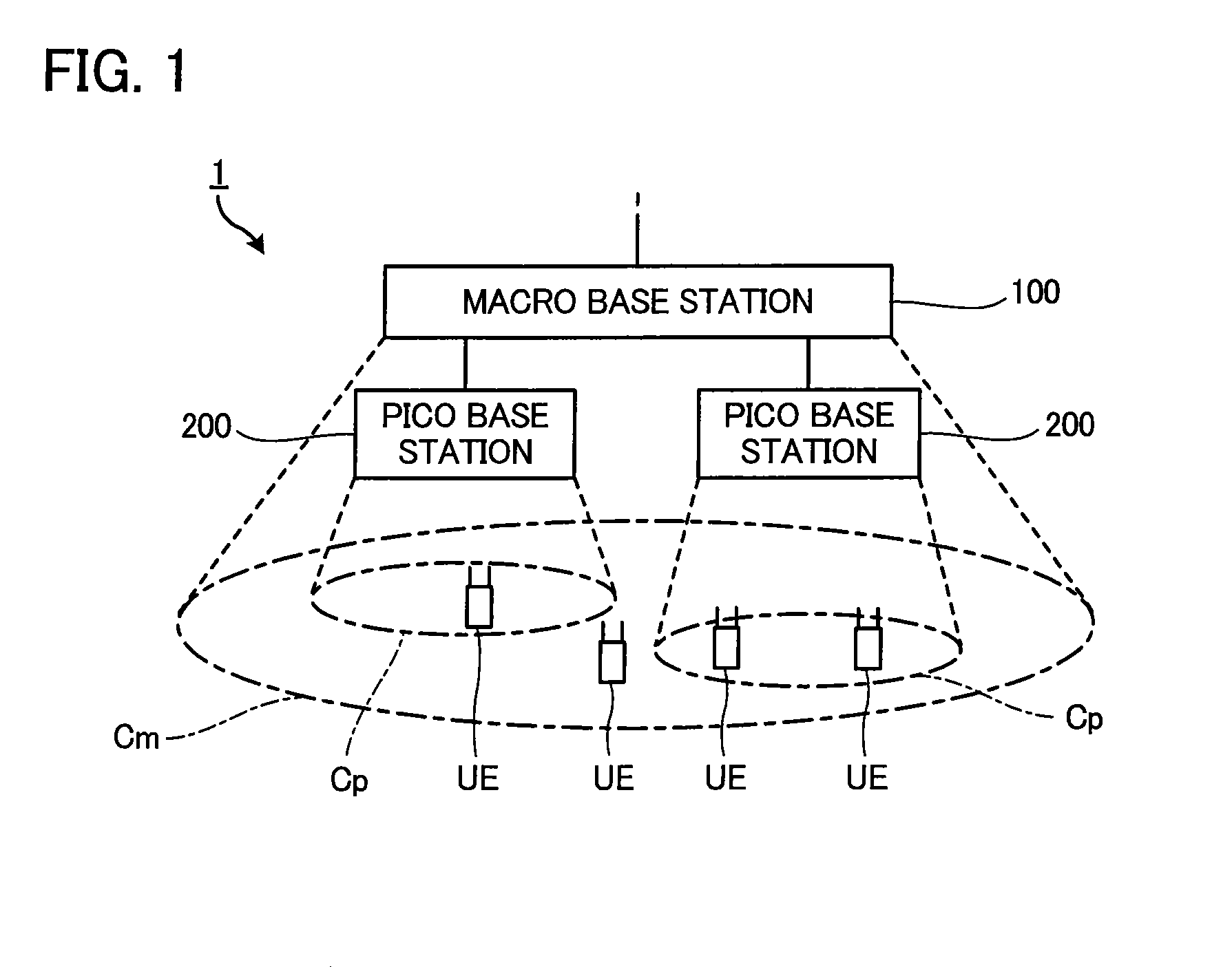
[0037]FIG. 1 is a block diagram illustrating a radio communication system 1 according to an embodiment of the present invention. The radio communication system 1 includes a macro base station (macro eNodeB (evolved Node B)) 100, a pico base station (pico eNodeB) 200, and a user terminal (user equipment) UE. Although the single macro base station 100 is shown in the figure for simplicity, it would naturally be understood that the radio communication system 1 could include multiple macro base stations 100.

[0038]Radio communication between each communication component (the macro base station 100, the pico base station 200, the user terminal UE, etc.) in the radio communication system 1 is performed according to a predetermined Radio Access Technology, such as LTE (Long Term Evolution). Although the present embodiment describes an example in which the radio communication system 1 operates according to LTE, it is not intended to limit the technic...

second embodiment

[0120]A second embodiment of the present invention is described below. In each embodiment described below, for an element for which operation and function are equivalent to those of the first embodiment, the reference symbols used in the above description are used, and description thereof will be omitted as appropriate.

[0121]As described in “(6) Cell Range Expansion”, by adding the bias value ‘a’ to the received power from the pico base station 200, the area of the picocell Cp formed by the pico base station 200 is pseudo-expanded.

[0122]FIG. 16 illustrates a state of the picocell before expansion (before-expansion picocell RP-Cp) and after Cell Range Expansion (after-expansion picocell CRE-Cp). Hereafter, the user terminal UE located inside the before-expansion picocell RP-Cp is referred to as a “user terminal RP-UE”, and the user terminal UE connected to the pico base station 200 by the Cell Range Expansion is referred to as a “user terminal CRE-UE”.

[0123]The allocated resource gro...

third embodiment

[0129]In the embodiments described above, the macro base station 100 (the radio communication unit 110) transmits radio signals to the user terminal UE in the non-protected subframe NSF and stops transmitting radio signals in the protected subframe PSF. On the other hand, the macro base station 100 (the radio communication unit 110) of the present embodiment transmits radio signals in the protected subframe PSF as well.

[0130]FIG. 17 is a diagram illustrating transmission power of the radio signals transmitted by base stations (the macro base station100, the pico base station 200) of the present embodiment. The radio communication unit 210 of the pico base station 200, in a manner similar to that in the aforementioned embodiments, transmits radio signals to the user terminal UE in both the protected subframe PSF and the non-protected subframe NSF. The radio communication unit 110 of the macro base station 100, in the non-protected subframe NSF, transmits radio signals in a manner sim...


PUM


Abstract

A user terminal reports a group radio quality of each of radio resource groups to a base station at a first frequence. The base station reports an allocated radio resource group to be allocated for radio communication with the user terminal to the user terminal. The user terminal reports unit radio qualities of radio resource units contained in the allocated radio resource group to the base station at a second frequence that is higher than the first frequence. The base station performs radio resource scheduling on the basis of the unit radio qualities.

Description

TECHNICAL FIELD[0001]The present invention relates to radio communication systems, base stations, user terminals, and communication control methods.BACKGROUND ART[0002]Technologies to allocate radio resources on the basis of measured qualities of radio resources have been known (e.g., radio connection destination selecting and frequency scheduling). However, receiving qualities are not uniform over all radio resources; for instance, receiving qualities could change in every time period or with respect to each frequency. Thus, a technology in which a radio quality of each radio resource unit (e.g., if a radio resource is a predetermined frequency band, then a partial frequency band contained in the frequency band is a radio resource unit) contained in radio resources is measured and reported to a base station by a user terminal has been suggested (e.g., Patent Document 1).CITATION LISTPatent Document[0003]Patent Document 1: Japanese Patent Application Publication No. 2008-048319SUMMA...

Claims


Application Information

Patent Timeline
Patent Type & Authority Patents(United States)
IPC IPC(8): H04W72/00H04W72/08H04L5/00
CPCH04W72/085H04W72/087H04L5/006H04W84/045H04W72/542H04W72/543
Inventor MIKI, NOBUHIKOJEONG, MOO RYONG
Owner NTT DOCOMO INC
Why Eureka
Try Eureka