Detection of particle contamination on wafers

a technology of particle contamination and semiconductor wafers, which is applied in the direction of beam/ray focussing/reflecting arrangement, electric discharge lamps, instruments, etc., can solve the problems of failure of devices at faster rates, and contamination of semiconductor devices, so as to achieve unprecedented sensitivity and reliability of contamination particle detection

Inactive Publication Date: 2015-04-30
GLOBALFOUNDRIES INC
View PDF4 Cites 3 Cited by
  • Summary
  • Abstract
  • Description
  • Claims
  • Application Information

AI Technical Summary

Benefits of technology

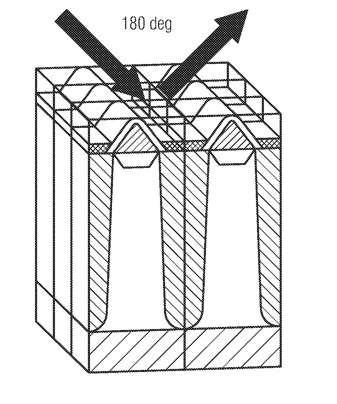
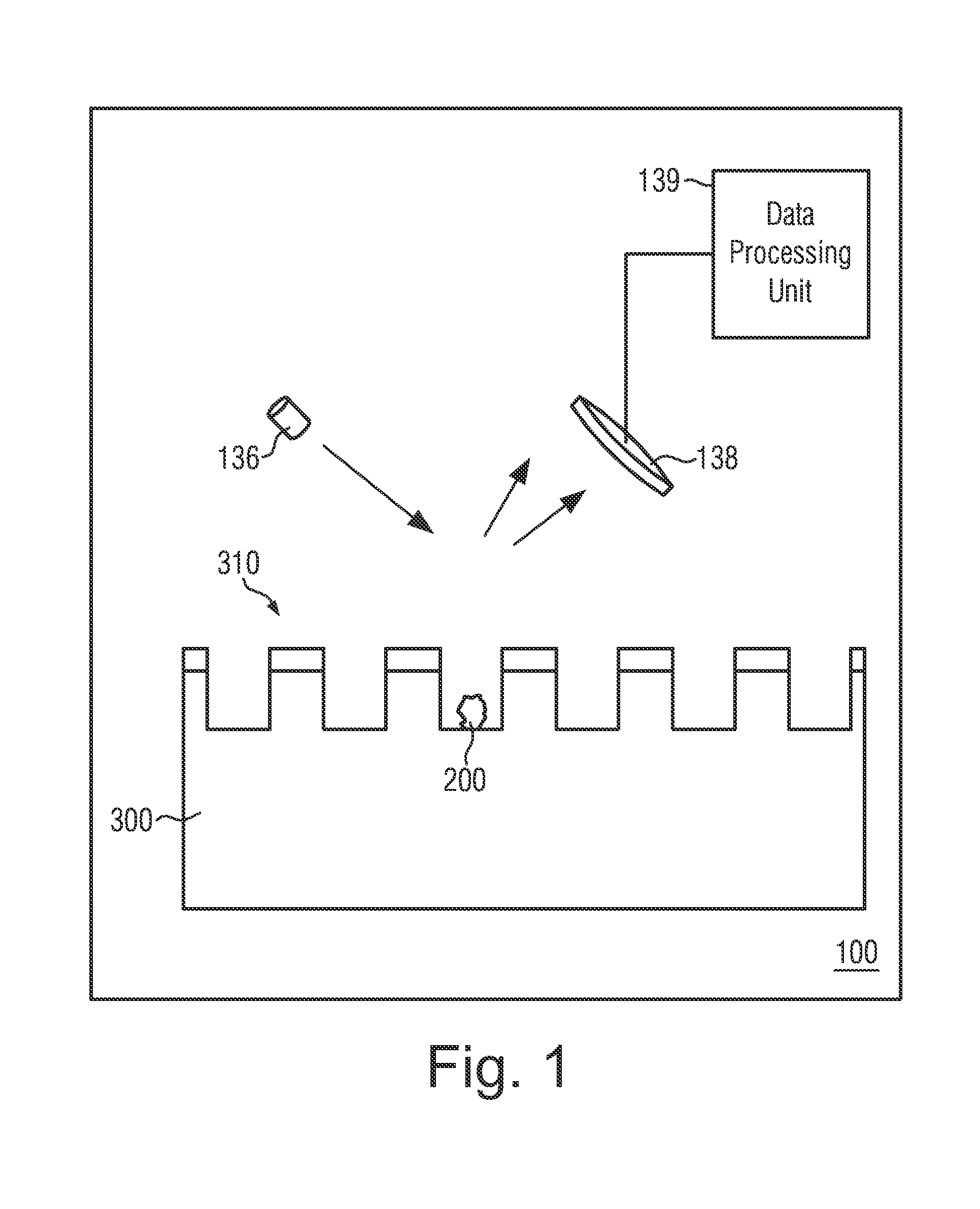
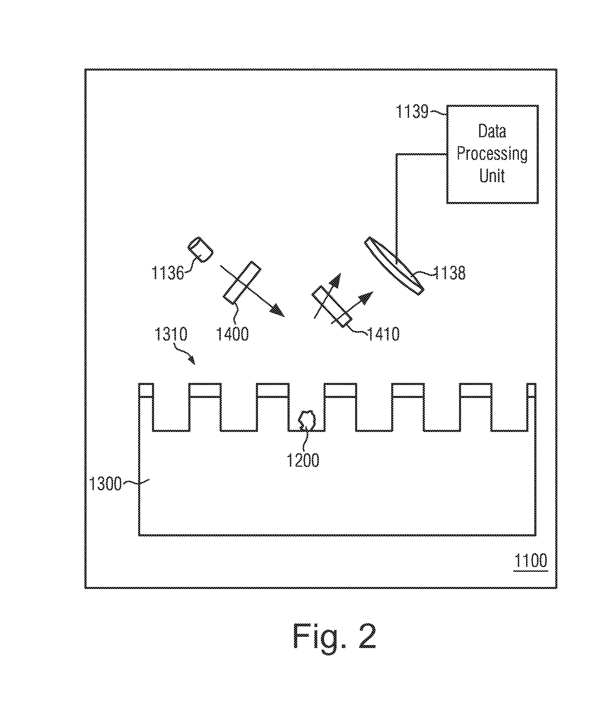
[0012]Metrology techniques are conventionally used for overlay control and determination of the spatial dimensions of features, for example, the thicknesses of polysilicon or nitride layers, a critical dimension of a polysilicon layer or a width of a sidewall spacer formed at a sidewall of a gate electrode. The inventors of the present invention surprisingly found out that metrology techniques may be useful for particle determination. An atypical use of present scatterometry or ellipsometry tools allows for an unprecedented sensitivity and reliability of contamination particle detection on processed semiconductor wafers. An illustrative method of the detection of particle contamination on a semiconductor wafer includes examining an area of the semiconductor wafer by a metrology system comprising a scatterometry or ellipsometry / reflectometry tool to obtain measured metrology data, comparing the measured metrology data with reference metrology data and determining the presence of particle contamination in the examined area of the semiconductor wafer based on the comparison of the measured metrology data with the reference metrology data.

Problems solved by technology

If not removed, contaminants on wafers and films may affect device performance characteristics and cause device failures to occur at faster rates than expected otherwise.
Nevertheless, semiconductor devices can become contaminated, and rendered defective, by contaminants during the various process steps.
For example, during the various processing steps, contaminants may be introduced from the numerous processing tools because of incomplete cleansing of reagents from the tools.
The reduction of particles at such small sizes is producing extreme challenges for original equipment manufacturers (OEMs) as they must tightly control the performance of every component within the equipment, in addition to reducing process defects.
The component suppliers face additional challenges as they not only have to meet the stringent performance specifications but also must improve performance based on continuously changing process latitudes and chemistries of end users.
One of the biggest challenges with such small defects is inspection and metrology.
However, sensibility for the detection of contaminating particles is not satisfying and state-of-the-art inspection tools can find defects only down to 30 nm on wafers and masks.
Inspection tools capable of detecting smaller sizes are presently not available.
Inspection and failure analysis tools that are capable of detecting defect sources below 50 nm are enormously costly, which causes a large infrastructure gap for suppliers working in component and material development.
Lacking that infrastructure, it is very difficult for many OEMs and subsystem, component and material suppliers to reduce defect sources and improve defect performance.
Tool downtime can be very costly as semiconductor processing is slowed or halted while the contamination source is located and cleaned.

Method used


Image

  • Detection of particle contamination on wafers
  • Detection of particle contamination on wafers
  • Detection of particle contamination on wafers

Examples


Embodiment Construction

[0022]Various illustrative embodiments of the invention are described below. In the interest of clarity, not all features of an actual implementation are described in this specification. It will of course be appreciated that in the development of any such actual embodiment, numerous implementation-specific decisions must be made to achieve the developers' specific goals, such as compliance with system-related and business-related constraints, which will vary from one implementation to another. Moreover, it will be appreciated that such a development effort might be complex and time-consuming, but would nevertheless be a routine undertaking for those of ordinary skill in the art having the benefit of this disclosure.

[0023]The present disclosure will now be described with reference to the attached figures. Various structures, systems and devices are schematically depicted in the drawings for purposes of explanation only and so as to not obscure the present disclosure with details whic...


PUM

PropertyMeasurementUnit
sizeaaaaaaaaaa
sizeaaaaaaaaaa
areaaaaaaaaaaa

Abstract

A method of the detection of particle contamination on a semiconductor wafer is provides which includes examining an area of the semiconductor wafer by a metrology system comprising a scatterometry or ellipsometry/reflectometry tool to obtain measured metrology data, comparing the measured metrology data with reference metrology data and determining the presence of particle contamination in the examined area of the semiconductor wafer based on the comparison of the measured metrology data with the reference metrology data.

Description

BACKGROUND OF THE INVENTION[0001]1. Field of the Invention[0002]Generally, the present disclosure relates to the field of the manufacture of integrated circuits and semiconductor devices, and, more particularly, to the detection of particle contamination of semiconductor wafers.[0003]2. Description of the Related Art[0004]The fabrication of advanced integrated circuits, such as CPUs, storage devices, ASICs (application specific integrated circuits) and the like, requires the formation of a large number of circuit elements on a given chip area according to a specified circuit layout. In a wide variety of electronic circuits, field effect transistors represent one important type of circuit element that substantially determines performance of the integrated circuits. Generally, a plurality of process technologies are currently practiced for forming field effect transistors, wherein, for many types of complex circuitry, MOS technology is currently one of the most promising approaches du...

Claims


Application Information

Patent Timeline
Patent Type & Authority Applications(United States)
IPC IPC(8): G01N21/95G01N23/00
CPCG01N23/00G01N21/9501G01N21/94
Inventor URBANOWICZ, ADAM MICHALHARTIG, CARSTENFISCHER, DANIEL
Owner GLOBALFOUNDRIES INC
Why Eureka
Try Eureka