Apparatus for gas cleaning

a technology for cleaning apparatus and gas, applied in lighting and heating apparatus, heating types, separation processes, etc., can solve the problems of fine white dust, marked decrease in cleaning efficiency, and substantial zero

Active Publication Date: 2018-04-17
VERSUNI HLDG BV
View PDF19 Cites 0 Cited by
  • Summary
  • Abstract
  • Description
  • Claims
  • Application Information

AI Technical Summary

Benefits of technology

[0006]To solve this problem, a humidifier can be used to increase the indoor RH. This increases the amount of water that is absorbed by the reagents and thus also their ability to absorb and / or react with specific gaseous pollutants in air. The reagents also exhibit high absorption efficiency towards specific gaseous target pollutants when the reagents are dissolved in water and the aqueous reagent solution is brought into contact with polluted air. This absorption is particularly efficient when the target gaseous pollutants also exhibit a high solubility in pure water. The humidifier is usually implemented by nebulisers or evaporators.
[0044]In an embodiment, the carrier is partitioned into different sections by vertically-positioned support plates. This is useful for separating the wetting- or drying-induced dimensional changes (such as shrinkage) in one part of the carrier from similar dimensional changes in other parts of the carrier, thereby avoiding the formation of additional gas passages at random locations in the carrier that may act as large by-passes for the gas wherein little or no gas cleaning occurs.

Problems solved by technology

The drawback of the air cleaning solution by means of impregnated reagents is that the cleaning efficiency markedly decreases when the relative humidity RH is below (<)40%-50% and becomes substantially zero when RH≤30%.
However, the use of a nebuliser may cause the deposition of a fine white dust throughout the room, while the use of an evaporator comprising a moistened wick or pad is hampered by scale formation in / on the wick / pad, which quickly reduces and eventually almost nullifies its effectiveness.
Additionally, undesirable growth of microbiological species in the water used for air humidification is a recurring problem requiring special attention and / or the application of biocidal agents for safeguarding the hygiene.
But at an airflow of more than 100 m3 / hr through the appliance, their performance is relatively poor, both with respect to their one-pass humidifying efficiency and with respect to their one-pass air cleaning efficiency towards gases like formaldehyde.
The reason is the highly pragmatic construction of these appliances and the unfavorable process conditions therein.
Another drawback of these appliances is that they always add moisture to the air during air cleaning, even when this is no longer desirable in case the relative humidity of the air is above 40-60%.

Method used


Image

  • Apparatus for gas cleaning
  • Apparatus for gas cleaning
  • Apparatus for gas cleaning

Examples


embodiment i

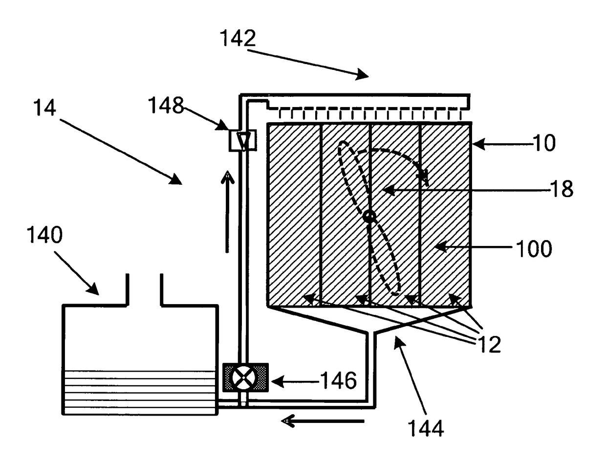
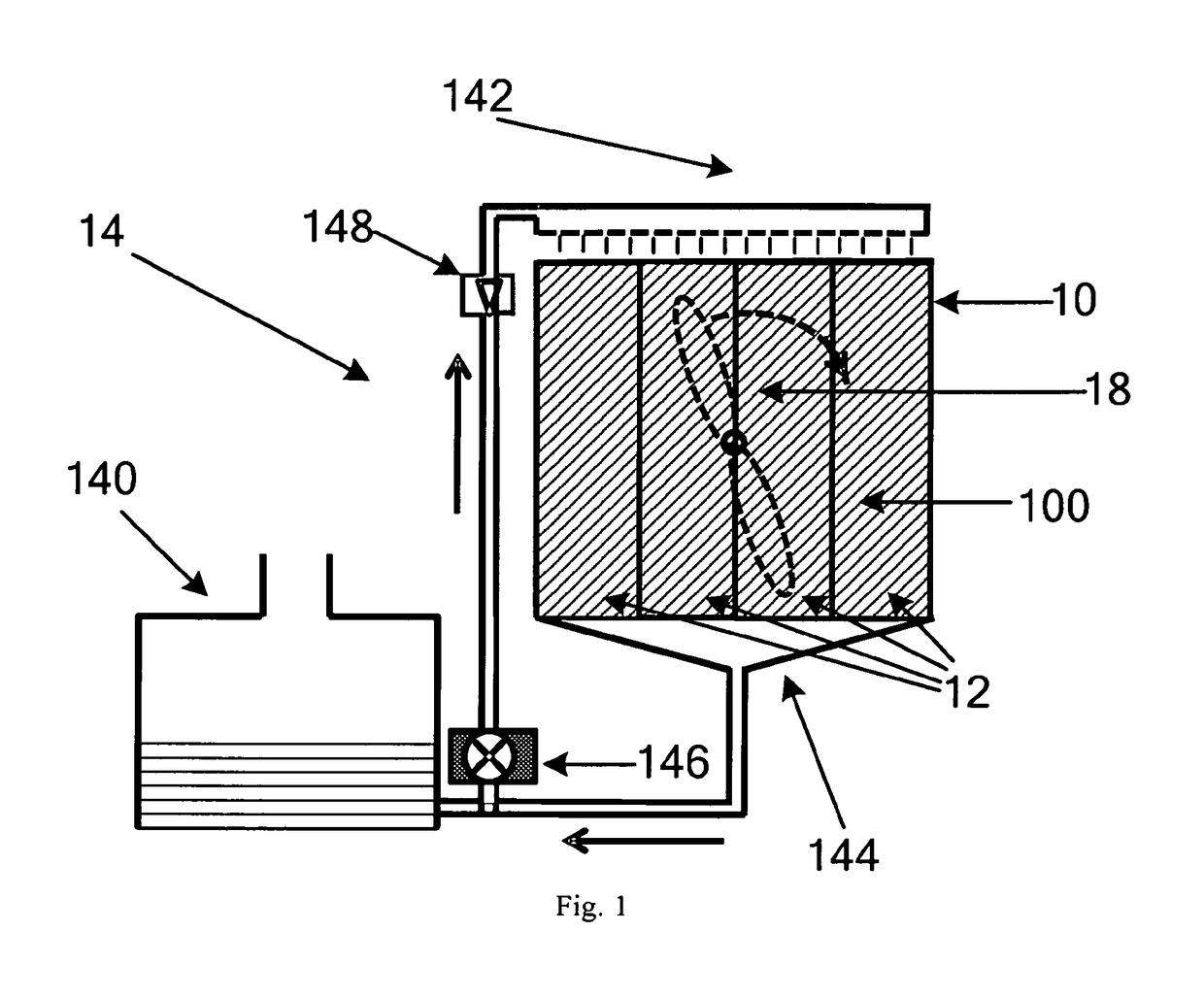
[0077]The liquid provided by the unit 14 to the carrier 12 is also the aqueous solution of the reagent that exhibits a physical or chemical reaction with the gaseous target pollutant, while the solvent can be water. When the gas with a low humidity passes through the carrier 12 that is wetted by the reagent solution, the gas becomes humidified through water evaporation from the wetted carrier surfaces. The gaseous pollutant that is soluble in water will at least partly dissolve in the reagent solution comprised in and on the carrier. The dissolved gaseous pollutant can then become strongly bound by the reagent in the solution through a chemical reaction or physical interaction, thereby enabling its removal from the gas.

embodiment ii

[0078]The unit 14 is provided with an inlet of tap water, and is controlled by the controller 16 to dispose water to the carrier 12. The water joins into the previously disposed solution of the reagent. When the gas with low humidity enters the carrier, the gas becomes humidified by the solution. The gaseous pollutant that is soluble in water will at least partly dissolve in the aqueous reagent solution contained in the carrier. The gaseous pollutant becomes thereby removed from the gas by reacting with the reagent in the aqueous reagent solution.

[0079]Besides reacting with the reagent, the pollutant gas is also at least partially dissolved in the solution, which also contributes to the gas cleaning.

[0080]In these embodiments, the apparatus for gas cleaning not only cleans the gas but also humidifies the gas.

[0081]● When the controller 16 determines that the humidity of the gas entering the carrier is above a second humidity threshold, the controller 14 triggers the unit 14 for disp...


PUM

PropertyMeasurementUnit
humidityaaaaaaaaaa
humidityaaaaaaaaaa
humidityaaaaaaaaaa

Abstract

The invention proposes an apparatus for gas cleaning having a high gas cleaning efficiency at any relative humidity. The apparatus comprises a passage (10) for gas flow; a hydrophilic carrier (12) permeable for gas flow, at least part of which is positioned within said passage for gas flow, and configured for containing a reagent that contacts the gas in said passage for gas flow; a unit (14) for disposing liquid to said carrier; and a controller (16), associated with said unit for disposing liquid, configured for controlling the unit for disposing to dispose an aqueous solution of dissolved reagent to the carrier; and after that controlling the unit for disposing to dispose liquid in case the humidity of the gas is below a first humidity threshold, or to stop disposing liquid in case the humidity of the gas is above a second humidity threshold.

Description

[0001]This application is the U.S. National Phase application under 35 U.S.C. § 371 of International Application No. PCT / IB2013 / 051446, filed on Feb. 22, 2013, which claims the benefit of U.S. Provisional Application No. 61 / 604,027 filed on Feb. 28, 2012. These applications are hereby incorporated by reference herein.TECHNICAL FIELD[0002]The disclosure relates to the field of gas cleaning.BACKGROUND ART[0003]Indoor air pollution is a known and persistent problem that affects people's health and well-being. A particular issue is the indoor air pollution with formaldehyde gas. For instance, the indoor air in many places suffers from formaldehyde pollution due to the widespread unregulated use of low-cost building and decoration materials comprising urea-formaldehyde resins. Adequate ventilation with outdoor air is a good remedy to remove the formaldehyde pollution. But the mechanical ventilation with filtered and temperature-conditioned outdoor air is only rarely encountered in common...

Claims


Application Information

Patent Timeline
Patent Type & Authority Patents(United States)
IPC IPC(8): B01D47/00B01D53/14B01D53/78F24F3/16F24F11/00B01D47/14B01D53/34F24F8/125
CPCB01D53/1412B01D47/14B01D53/78F24F3/16F24F11/30F24F2110/20Y02B30/78B01D53/346B01D2247/04B01D2247/08B01D2251/2067B01D2251/304B01D2251/306B01D2251/606B01D2252/204B01D2252/205B01D2257/302B01D2257/406B01D2257/702F24F2003/1617F24F2003/1621F24F2110/66F24F8/15Y02B30/70F24F8/125
Inventor MARRA, JOHAN
Owner VERSUNI HLDG BV
Why Eureka
Try Eureka