
Comprehensive RFID and radio communication test system

a comprehensive and radio communication technology, applied in the field of rfid tag testing systems, can solve the problems of complex and significant challenges faced by rfid test system designers, and achieve the effect of extreme accuracy

Inactive Publication Date: 2018-04-17
MET LAB INC
View PDF5 Cites 0 Cited by
  • Summary
  • Abstract
  • Description
  • Claims
  • Application Information

AI Technical Summary

Benefits of technology

[0008]Accordingly, it is an object of the present invention to provide an improved apparatus for testing various types of RFID tag and reader combinations especially in the context of electronic toll collection systems, capable of passing the RFID tag within an adjustable range of a reader at an adjustable speed a large number of times, all with extreme accuracy.
[0010]It is further an object of the present invention to provide such a system that is scalable to allow testing of various sizes of RFID tag and reader combinations and at increasing volumes.
[0011]It is further an object of the present invention to provide a testing system that is safe for the operator, equipment, and surroundings.
[0012]These and other features and benefits are achieved with an improved radio RFID tag and reader system comprising a reduced scale and scalable vehicle fitted with one or more electronic toll collection RFID tags and a track on which the vehicle may operate at a high rate of speed for long periods of time with minimal friction and without derailing or fatigue to the structure of either vehicle or track. The inventive testing system further utilizes a novel vehicle propulsion system comprising a custom designed synchronized motor chive with two or more balanced wheels to maintain a variable and accurate speed of the vehicle upon each pass by the reader.

Problems solved by technology

However, the current demand is driving mounting pressure to improve tag performance to achieve read rates closer to 100% at higher speeds, RFID test system designers face a significant challenge when attempting to meet the needs of this emerging market.
Comprehensive RFID testing is complex, and entails a combination of conformance, interoperability and lifecycle testing.

Method used


Image

  • Comprehensive RFID and radio communication test system
  • Comprehensive RFID and radio communication test system
  • Comprehensive RFID and radio communication test system

Examples


Embodiment Construction

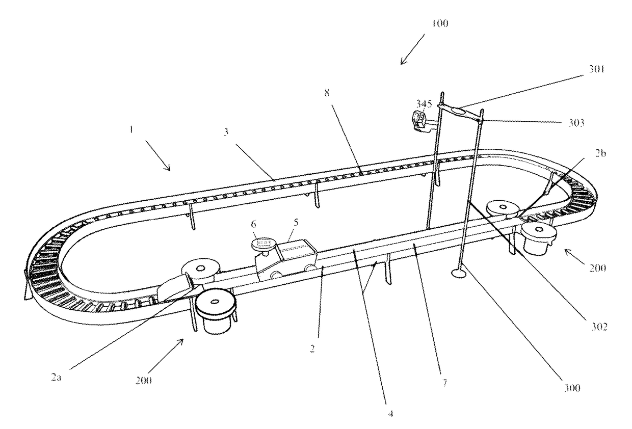
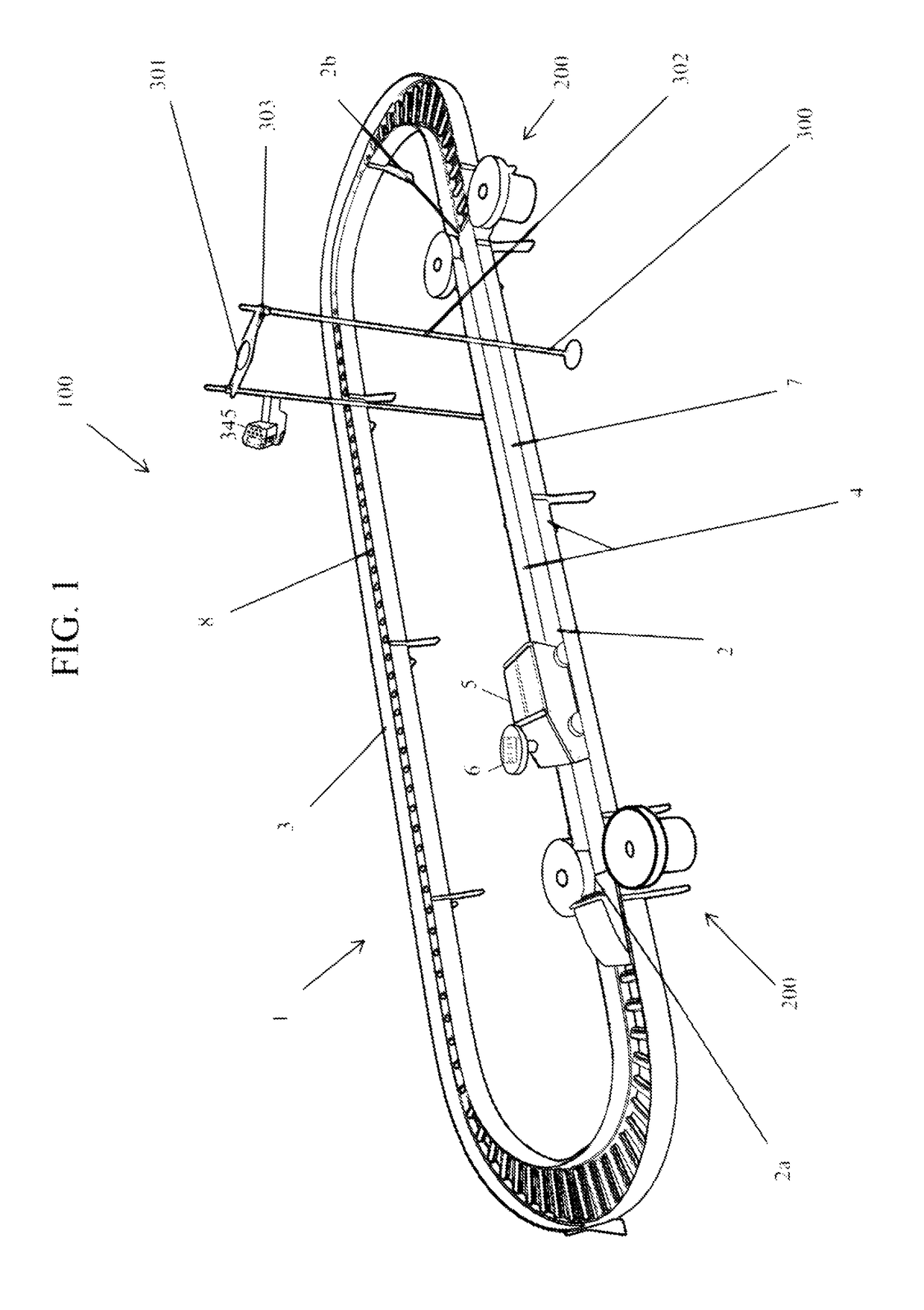
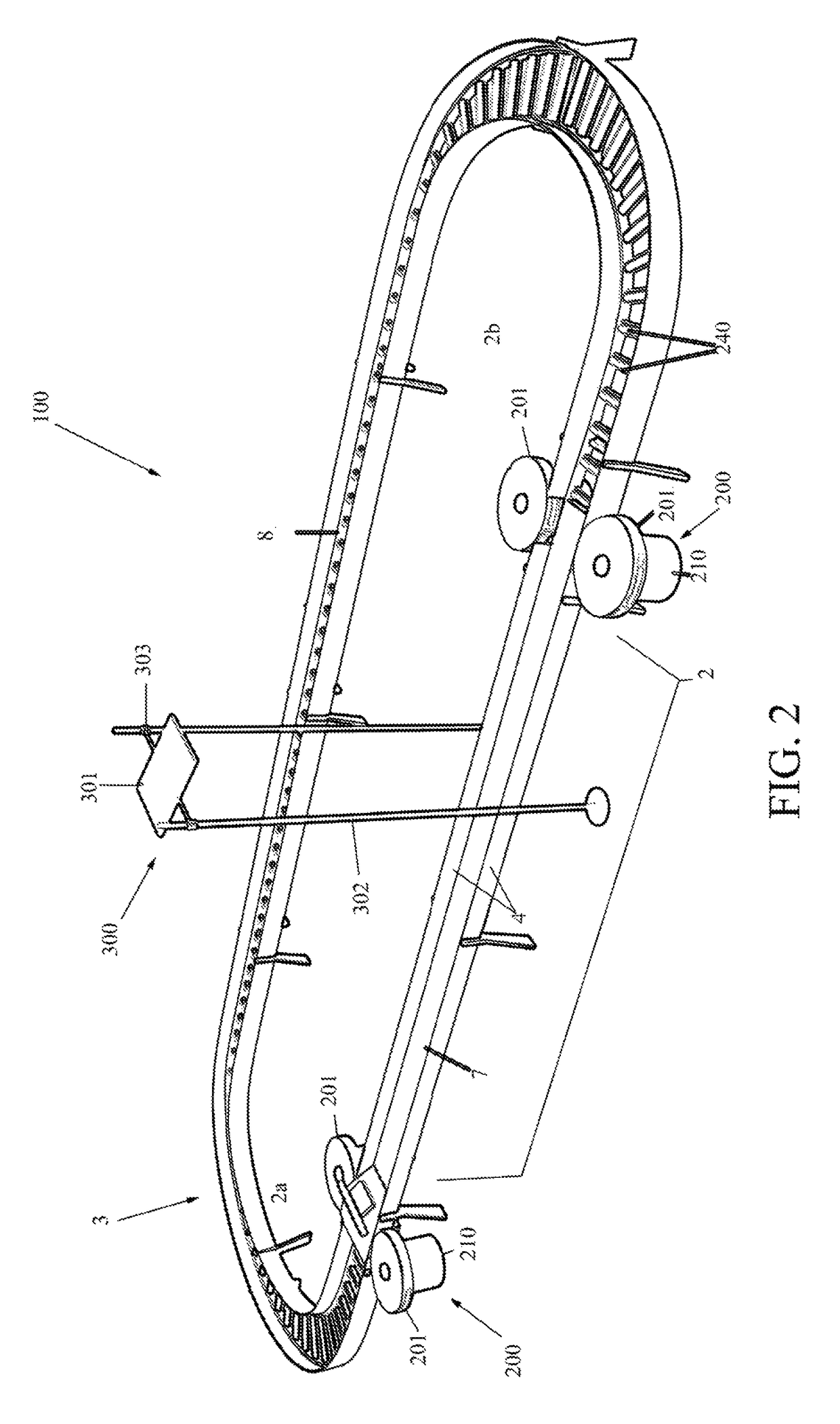
[0019]As seen in FIG. 1, a comprehensive test system 100 for testing RFID tag / reader combinations according to an embodiment of the invention generally comprises a track 1 forming a closed circuit or loop, most preferably in the shape of an extended oval, and fitted with one or more rotating-wheel propulsion mechanisms 200. In addition, at least one portal 300 is provided comprising an elevated mount for supporting an RFID reader of antenna directly above the track 1. A passive moving vehicle 5 rolls and / or slides freely on the track 1. In a preferred embodiment the moving vehicle 5 is constrained on the track 1 by vertical sidewalls, but one skilled in the art will understand that a slot-car mechanism is also possible as described below. Vehicle 5 is sized as necessary as a matter of design choice to carry one or more electronic toll collection RFID tags 6 being tested. The portal 300 comprises a pair of vertical freestanding legs with a height-adjustable cross-beam mounted there a...


PUM


Abstract

An improved radio RFID tag and reader system comprising a reduced scale and scalable vehicle fitted with one or more electronic toll collection RFID tags and a track on which the vehicle may operate at a high rate of speed for long periods of time with minimal friction and without derailing or fatigue to the structure of either vehicle or track. The inventive testing system further utilizes a novel vehicle propulsion system comprising counter-rotating wheels adapted to maintain a variable and accurate speed of the vehicle upon each pass by the reader. The propulsion mechanism propels the vehicle down the track past the reader and returns it to a starting point to provide repeated interaction between RFID tag and reader.

Description

CROSS-REFERENCE TO RELATED APPLICATION(S)[0001]The present application derives priority from U.S. Provisional Patent Application Ser. No. 62 / 153,777 filed Apr. 28, 2015.BACKGROUND OF THE INVENTION[0002]1. Field of the Invention[0003]The present invention relates generally to RFID tag testing systems and, more specifically, to a system for repeatedly propelling a vehicle around a track to automate the process for testing an electronic toll collection reader and RFID tag system.[0004]2. Description of the Background[0005]Radio-frequency identification (RFID) entails the wireless use of radio waves between an RFID tag and a tag reader for the purpose of automatically identifying and tracking an object. The RFID tag includes a RFID tag, capable of receiving a wireless signal, termed an interrogating signal, and responding by emitting an identifying signal unique to the RFID tag. There are a variety of applications for this technology, and RFID tags can be attached to most anything inclu...

Claims


Application Information

Patent Timeline
Patent Type & Authority Patents(United States)
IPC IPC(8): G08G1/01G01R31/28G07B15/06G06K7/00
CPCG06K7/0095G07B15/063G01R31/2822
Inventor FRIER, ROBERT
Owner MET LAB INC
Learn More