Rotary Die Axis Synchronization System and Adjustable Wedge Apparatus Therefor

a wedge apparatus and synchronization system technology, applied in the direction of metal working apparatus, etc., can solve the problems of deflection of the die roll, inability to adjust the wedge apparatus, and the necessary roll diameter can be too large for many applications, and achieve the effect of accurate die positioning and extreme accuracy

Inactive Publication Date: 2022-04-14
BERNAL LLC
View PDF0 Cites 0 Cited by
  • Summary
  • Abstract
  • Description
  • Claims
  • Application Information

AI Technical Summary

Benefits of technology

[0008]It is another object of the present invention to provide a mounting and positioning system that provides extremely accurate positioning of the die with respect to a web and an anvil roll, including positioning vertically, axially, and circumferentially.
[0009]Yet another object of the present invention is to provide a rotary die cutter positioning and mounting system wherein adjustments can be made with extreme accuracy, independently of one another, and while the die cutter is operating.
[0010]It is yet another object of the present invention to provide a rotary die cutter mounting and positioning system that can be set up or adjusted within an extremely short make-ready time as compared to conventional systems currently in use.

Problems solved by technology

Problems arise due to the deflection of the die roll caused by operating forces, machine distortions, vibrations, and thermal expansions.
While this can work, the necessary roll diameter can be too large for many applications.
Moreover, there is a disadvantage in that such a die cylinder can be large and costly to manufacture.
In addition, the substantial rotational inertia of such a large diameter die roll is an impediment to achieving a fast stop in the case of an emergency stop.
Other disadvantages relate to the need to have the apertures extremely accurately located so that they are in registration with the pattern printed on a web.
The adjustment process is manual, time-consuming, and cannot be made on the run.
Also, eccentric adjustments do not provide the fine degree of adjustment often required to compensate for wear or the other factors listed above.
This web shift has a significant disadvantage in that it requires that all of the other pieces of equipment in the line, such as gluers, perforators, numbering machines, plow stations, and combinations thereof also be adjusted with respect to the web to maintain registration.
This multiple adjustment of a series of machines to the web shift is time-consuming and tedious.

Method used


Image

  • Rotary Die Axis Synchronization System and Adjustable Wedge Apparatus Therefor
  • Rotary Die Axis Synchronization System and Adjustable Wedge Apparatus Therefor
  • Rotary Die Axis Synchronization System and Adjustable Wedge Apparatus Therefor

Examples


Embodiment Construction

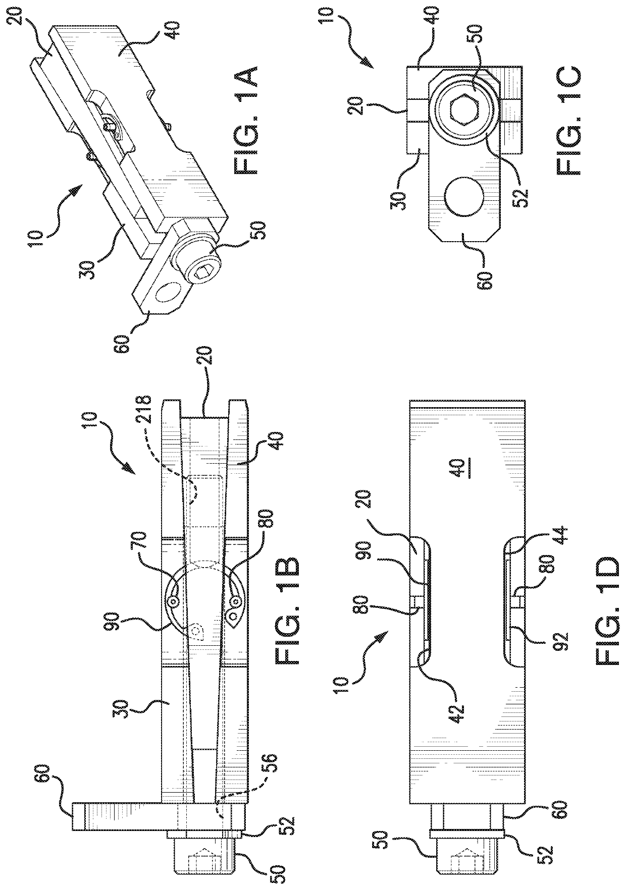
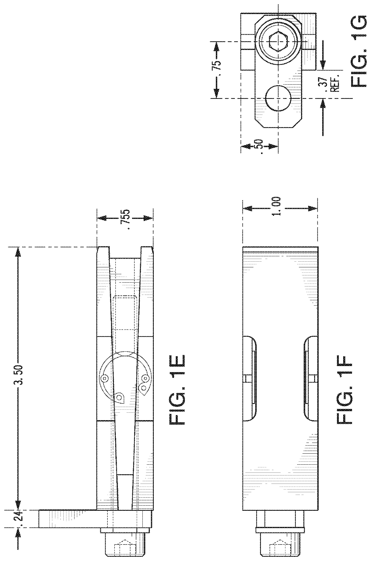
[0040]The present invention provides an adjustable wedge apparatus that can be tightened or loosened to increase or decrease the spacing it provides and adjust skew in a rotary die cutter. The adjustable wedge apparatus comprises a split wedge, a first block, a second block, a threaded adjustment screw, and an expandable and contractable biasing device. The split wedge is configured to be sandwiched between the first block and the second block. The first block and the second block are configured to be held together, with the split wedge there between, by the expandable and contractable biasing device. The threaded adjustment screw can be rotated to expand or contract the spread provided between the first block and the second block.

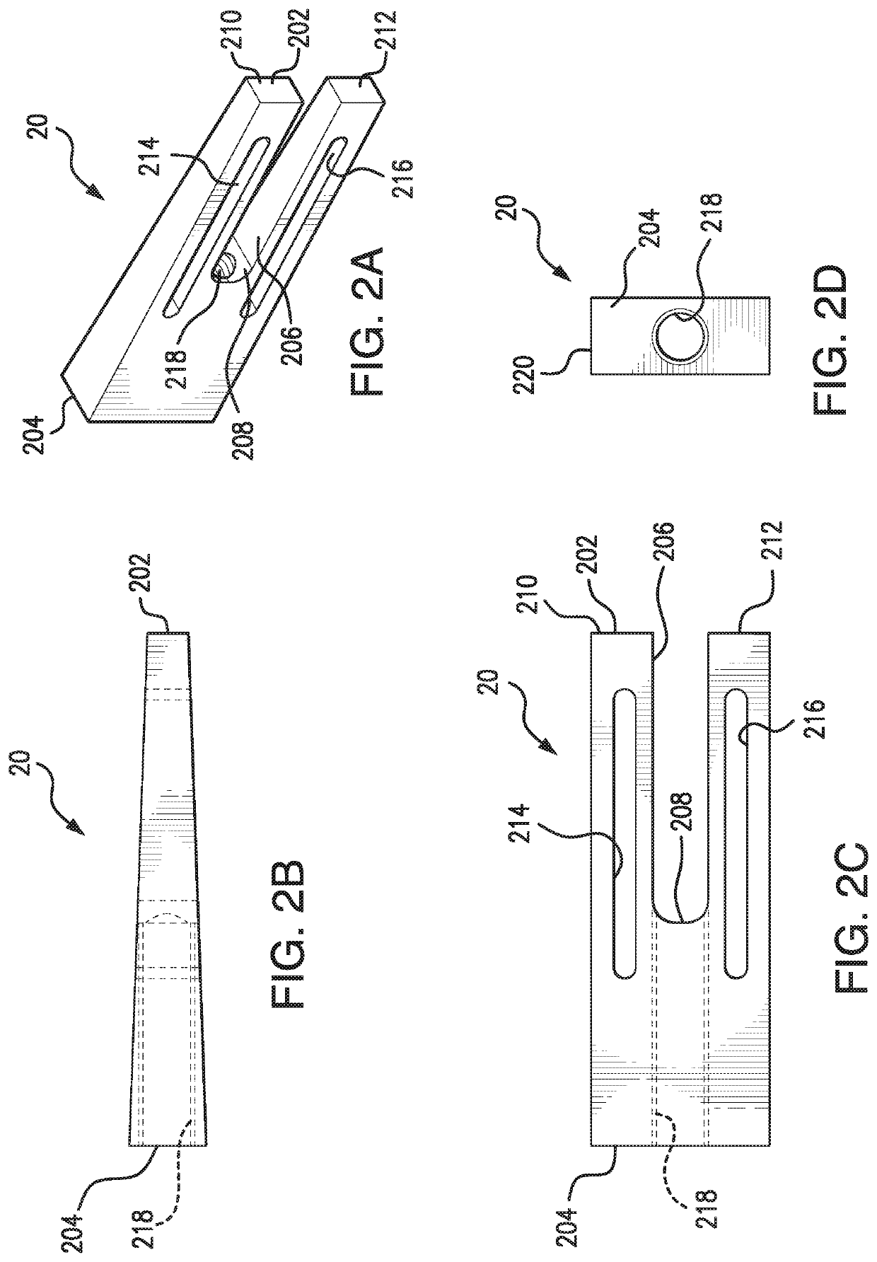
[0041]The split wedge has a blunt end, a narrow end, a recess, a through-hole, and a pair of through-slots. The recess has an opening at the narrow end, which extends toward the blunt end. The recess also has a recess bottom. The recess divides the narrow ...


PUM


Abstract

An adjustable wedge apparatus is provided that includes a split wedge, a first block, a second block, a threaded adjustment screw, and an expandable and contractable biasing device. The split wedge is configured to be sandwiched between the first block and the second block. The first block and the second block are configured to be held together, with the split wedge between, by the expandable and contractable biasing device. The spilt wedge has a narrow end divided into two tines, and a threaded through-hole. The threaded adjustment screw has an external thread that is complementary to the internal thread of the through-hole. Tightening the threaded adjustment screw spreads apart the first block and the second block. An axle alignment system including the adjustable wedge apparatus is also provided, for example, a rotary die cutter alignment system. A method skew of adjustment is also provided.

Description

FIELD OF THE INVENTION[0001]The present invention relates to systems and processes for mounting and positioning rotating rolls in a rotary die. More specifically, the present invention relates to a roll mounting and positioning system.BACKGROUND OF THE INVENTION[0002]Rotary die cutters are well known for cutting apertures of various sizes and shapes in a running web, particularly a web operating in conjunction with a printing press. An exemplary application of such die cutters is to cut peel-off labels carried on a backing sheet. Known rotary die cutters utilize a pair of rolls rotating about two parallel axes that are rotatably mounted between a pair of side frames. The rolls are driven by a line shaft. One roll, designated as the die roll, or cylinder, carries flexible sheet metal dies on its outer surface, which include cutting and creasing lands. Each die is formed from a thin metal sheet and has raised lands formed in the shape of an aperture to be cut and crease lines to be fo...

Claims


Application Information

Patent Timeline
Patent Type & Authority Applications(United States)
IPC IPC(8): B26D7/26B26D7/20
CPCB26D7/2635B26D7/20B26D7/265B26D2007/2692B26F1/384
Inventor GROULX, RICHARD EARL
Owner BERNAL LLC
Why Eureka
Try Eureka