Method for parallel operation of reactors that generate moisture

a technology of generating reactors and reactors, which is applied in the direction of water, gas-gas reaction processes, transportation and packaging, etc., can solve the problems of temperature rise, internal temperature rise, and approach, and achieve the effects of reducing cost, extreme accuracy, and safe supply

Inactive Publication Date: 2010-06-10
FUJIKIN INC
View PDF5 Cites 0 Cited by
  • Summary
  • Abstract
  • Description
  • Claims
  • Application Information

AI Technical Summary

Benefits of technology

[0023]In accordance with the present invention, mixed gas, which is a source gas used to generate moisture, can be allowed to branch off with extreme accuracy by using a flow-dividing structure having a simple construction in which an orifice having a predetermined opening diameter is only disposed on the mixed-gas inlet side of each of the moisture generating reactors connected in parallel with each other, and a large amount of high-purity water can be supplied using a non-combustion type moisture generating reactor that employs a conventional platinum coating catalyst. In other words, according to the present invention, a large amount of high-purity water can be supplied safely, and at lower cost, by using a conventional non-combustion type moisture generating reactor without using a mixed-gas-flow-dividing apparatus that is high in cost, and complex in structure, and without having to enlarge the equipment to supply the large amount of high-purity water.

Problems solved by technology

However, in the moisture generating reactor shown in FIG. 8, if the supply of the source gas G is increased in amount so as to increase the amount of moisture generation, a rise in temperature of the outlet-side reactor body member 3 becomes steep, and the temperature of the internal space of the reactor body 1 will rise and approach the explosive temperature of the source gas G, which is H2—O2 mixed gas, and, as a result, an extremely dangerous state will be reached.
Additionally, if the supply of the source gas G is increased in amount, the rate of reaction between hydrogen H2 and oxygen O2 will fall, and oxygen O2 and hydrogen H2 will enter into, and mix with, moisture gas W without allowing oxygen O2 and / or hydrogen H2 to react with each other, and, as a result, various disadvantages will occur on the process side where the moisture gas W is used.
Additionally, if the temperature of the reactor body 1 rises, the platinum coating film 9 formed on the inner wall surface of the outlet-side reactor body member 3 will peel and fall off, and, as a result, a significant deterioration in catalytic action will result.
However, a problem resides in the fact that the disposition of the cooling fins 10 and 11 leads to a great increase in outside dimensions of the moisture generating reactor 1, and, if the amount of moisture generation is made, for example, 1.3 times as great as the conventional amount of moisture generation, the volume of the reactor 1 must be tripled, and hence it is impossible to meet the requirement of reducing the moisture generating reactor 1 in size.
However, if the area in which the platinum coating film 9 is formed exceeds a predetermined area, unevenness will occur in the temperature distribution on the inner surface of the outlet-side reactor body member 3 when moisture is generated, and, as a result, the platinum coating film 9 may readily peel off.
Therefore, another problem resides in the fact that, if the inner diameter of the reactor body 1 is made, for example, twice or more as large as the conventional one, the frequency of occurrence of peeling off of the platinum coating film 9 will rise steeply, as is well known, and the requirement of increasing the amount of moisture generation cannot be satisfactorily met.
However, still another problem resides in the fact that the disposition of the highly accurate apparatus for dividing the flow of the mixed gas G, and supplying the gas, brings about not only a steep rise in the amount of equipment employed, but also brings about the need for a large space for the installation of the equipment, and furthermore, it increases costs for the maintenance, or the like, of the mixed-gas-flow-dividing-and-supplying apparatus.

Method used


Image

  • Method for parallel operation of reactors that generate moisture
  • Method for parallel operation of reactors that generate moisture
  • Method for parallel operation of reactors that generate moisture

Examples


exemplary embodiment 1

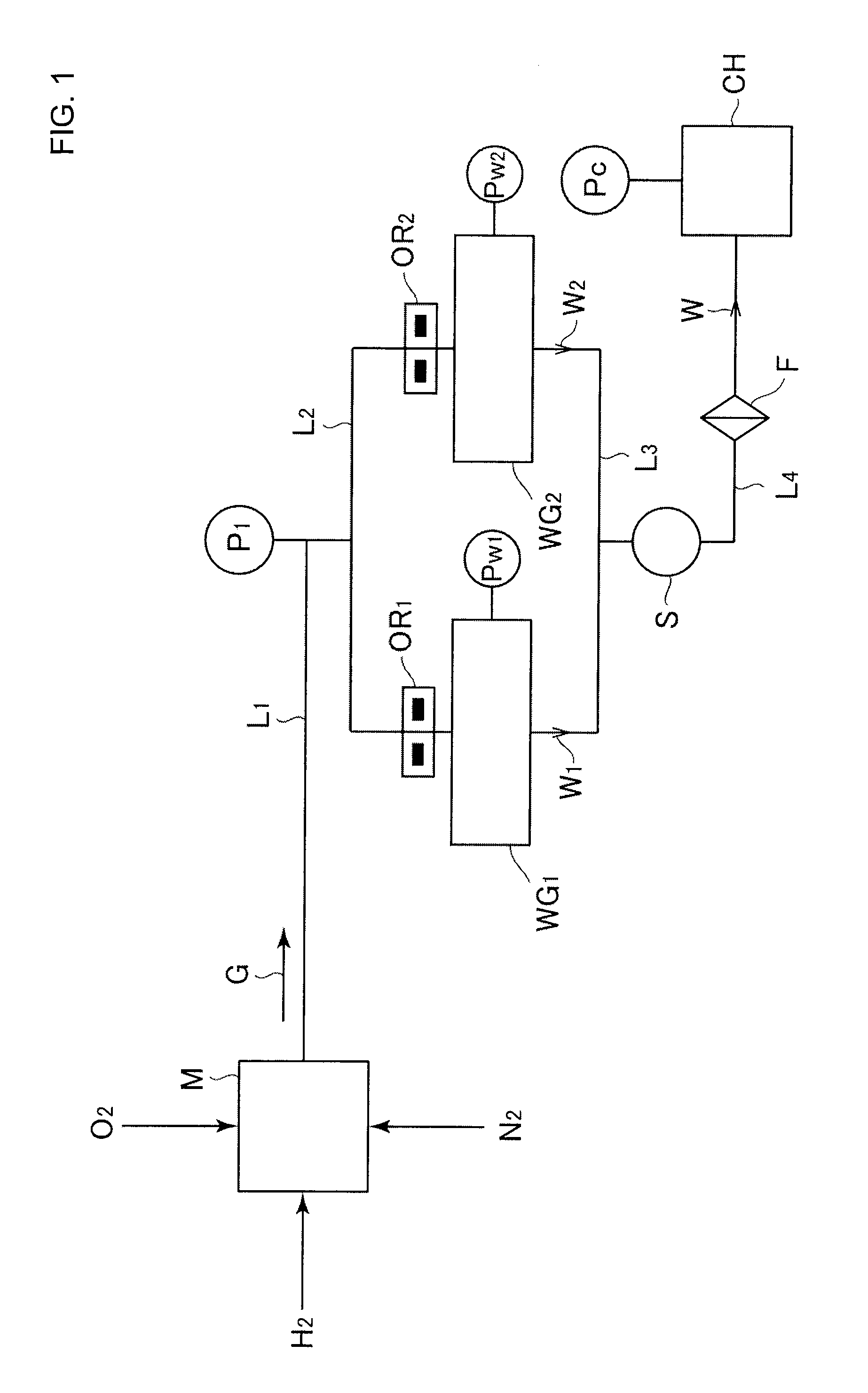
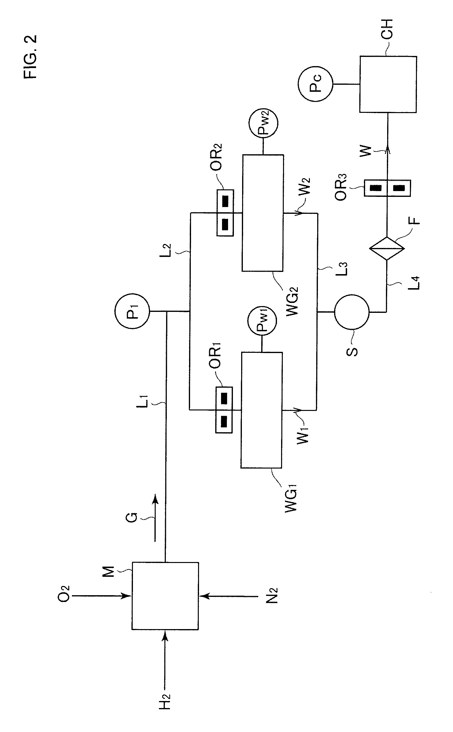
[0077]FIG. 5 is a system diagram wherein 17 SLM moisture gas W is supplied to the chamber CH, which operates under normal pressure (760 Torr), using the two moisture generating reactors WG1 and WG2. Table 5, below, shows orifice upstream-side pressures calculated from the flow rate Q and from the sectional area S on the assumption that a critical condition is established between the upper and lower streams of the orifices OR1 and OR2, shown in the system diagram of FIG. 5.

[0078]Formula (1) is the operational expression of the flow rate Q.

[Formula1]Q=SPHTH·C′·(F.F.)(1)

[0079]In this equation, Formula I, Q is a flow rate of gas, S is an orifice sectional area, TH is a temperature of gas, PH is upstream pressure, C is the constant 187021, and C′ is a correction (C×0.82) calculated from an actual flow rate.

TABLE 5SectionalStream belowOrificearea SStream above orificeorificemmmm2kPa absTorrTorr0.650.332202.61519.5759.80.60.283237.71783.4891.70.550.238282.92122.31061.20.50.196342.42568.012...

exemplary embodiment 2

[0080]In the same system diagrammed as that of FIG. 5, pressure P1 and pressure P2 on the upstream side (i.e., tube upstream side) and on the downstream side (i.e., above the orifices OR1 and OR2) of the mass flowmeter MFC have been respectively calculated when mixed gas G consisting of H2 and O2, corresponding to moisture generation of 17 SLM, is allowed to flow. Formulas (2) and (3) are operational expressions therefor.

[Formula2]Q=C(P1-P2)(2)[Formula3]C=π8ηa4l(p1+p22)(3)

[0081]In the equations of Formulas (2) and (3), Q is a flow rate of gas, P1 is upstream pressure, P2 is downstream pressure, a is an orifice radius, and η is a viscosity coefficient of the gas. When a tube pressure loss (H2 / O2) is calculated, the viscosity coefficient of mixed gas G cannot be calculated and, hence, a calculation is performed both for H2 and for O2 as shown in Table 6 (the viscosity coefficient η of H2 is 0.88×10⁻⁵ Pa·sec, and the viscosity coefficient ζ of O2 is 1.75×10⁻⁵ Pa·sec).

TABLE 6StreamSecti...

exemplary embodiment 3

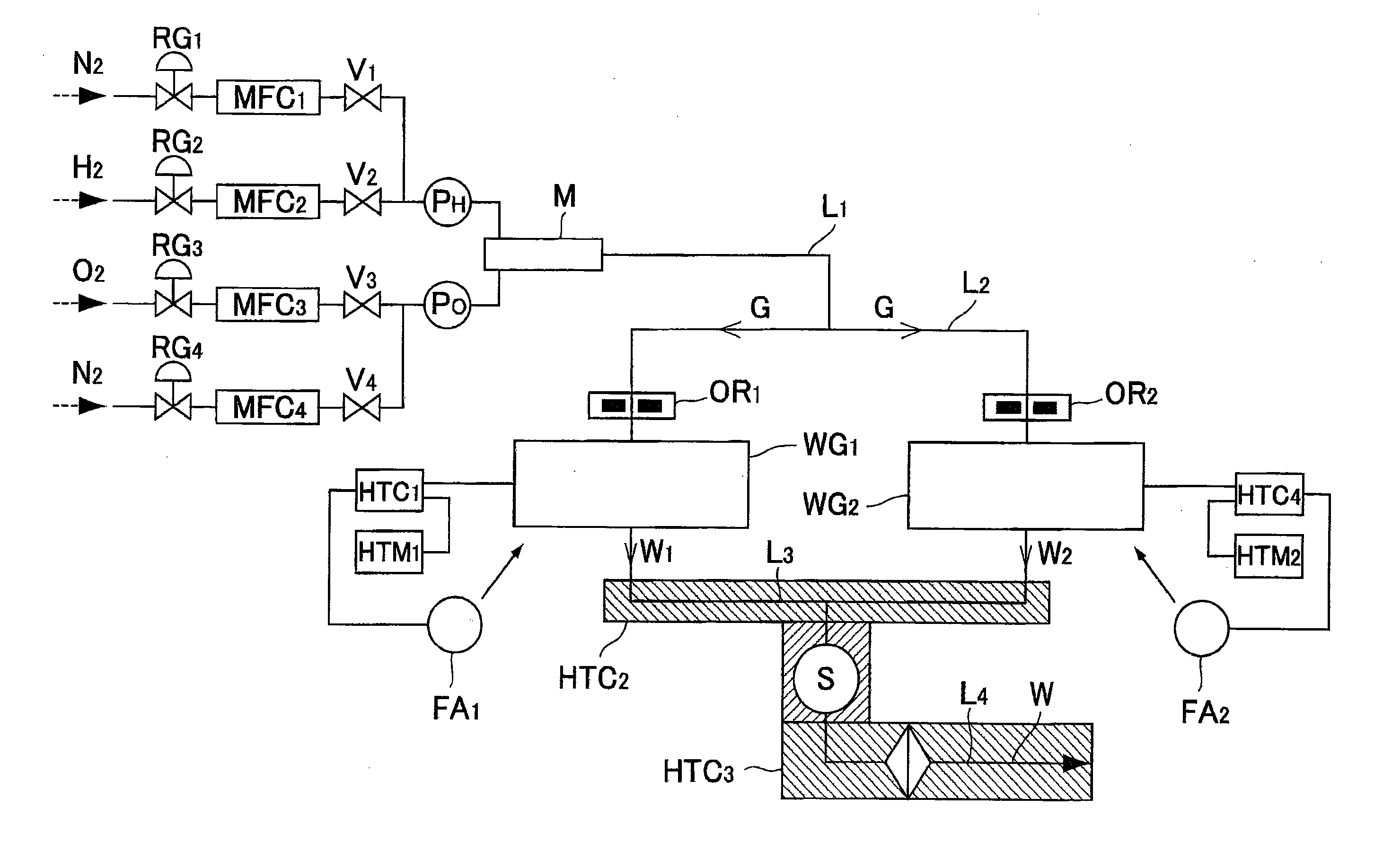
[0082]FIG. 6 is a system diagram showing parallel operation of two moisture generating reactors WG1 and WG2 performed according to the present invention. In FIG. 6, RG1 to RG4 designate pressure regulators, V1 to V4 designate valves, FA1 and FA2 designate cooling fans, HTC1, HTC2, HTC3, and HTC4 designate temperature controllers, and HTM11 and HTM2 designate temperature monitors. The outlet side of each of the moisture generating reactors WG1 and WG2 opens toward the atmosphere.

[0083]The temperature controllers HTC1 and HTC4 are used to keep the temperature of the moisture generating reactors WG1 and WG2 at 350° C., and the cooling fans FA1 and FA2 are controllably operated, if necessary. The temperature controllers HTC2 and HTC3 are used to keep the temperature of the tube lines at 140° C. Each of the orifices OR1 and OR2 is an orifice whose opening diameter is 0.7 mmφ, and each of the moisture generating reactors WG1 and WG2 is a 5 SLM type reactor having an outer diameter of 180 ...


PUM

PropertyMeasurementUnit
pressureaaaaaaaaaa
diameteraaaaaaaaaa
pressureaaaaaaaaaa

Abstract

The method for parallel operation of moisture generating reactors according to the present invention operates so that an orifice, provided with an orifice hole having a predetermined opening diameter, is disposed on a mixed-gas inlet side of each of a plurality of moisture generating reactors connected in parallel with each other, and mixed gas G consisting of hydrogen and oxygen is supplied from a mixer to each of the moisture generating reactors through each orifice, and the flows of moisture generated by the moisture generating reactors are combined, and the resulting combined moisture is supplied to an apparatus that uses high-purity water. Thus, a need to increase the amount of high-purity water supply is met by allowing a plurality of moisture generating reactors to perform a parallel water generating operation by branching off a mixed gas consisting of H2 and O2 by using a simple orifice construction.

Description

[0001]This is a National Phase Application in the United States of International Patent Application No. PCT / JP2007 / 000419 filed Apr. 17, 2007. The entire disclosure of the above patent application is hereby incorporated by reference.FIELD OF THE INVENTION[0002]The present invention relates to a method for the parallel operation of moisture-generating reactors that is used in, for example, semiconductor manufacturing facilities, or chemical manufacturing facilities, and that enables each moisture generating reactor to perform a stable parallel operation in a predetermined amount of moisture generation merely by inserting orifices, each of which has an appropriate opening diameter, into the source-gas supply lines of the moisture generating reactors, respectively, that perform a parallel operation without using a special apparatus that divides the flow of source gas and supplies the gas.BACKGROUND OF THE INVENTION[0003]For example, in silicon-dioxide-film adhesion processing according...

Claims


Application Information

Patent Timeline
Patent Type & Authority Applications(United States)
IPC IPC(8): C01B5/00
CPCC01B5/00Y10T137/0396B01J12/00
Inventor MINAMI, YUKIOHIRAO, KEIJITAGUCHI, MASAHARUNARIAI, TOSHIROKAWADA, KOJIMORIMOTO, AKIHIROIKEDA, NOBUKAZU
Owner FUJIKIN INC
Why Eureka
Try Eureka