High-speed wire rod rolling apparatus and method

a wire rod and high-speed technology, applied in the direction of metal rolling arrangements, cantilevered roll stands, manufacturing tools, etc., can solve the problems of affecting the quality of finished products, so as to achieve accurate control of the dimensional tolerances of finished products

Inactive Publication Date: 2013-04-11
DANIELI & C OFF MEC SPA
View PDF6 Cites 0 Cited by
  • Summary
  • Abstract
  • Description
  • Claims
  • Application Information

AI Technical Summary

Benefits of technology

[0015]It is the main object of the present invention to make a wire rod rolling apparatus which allows to vary the reduction percentage of the rolled product by operating on the motor rpm only, regardless of the diameter of the rolling rings and without the aid of mechanical shifts.
[0016]Another object of the present invention is to control with extreme accuracy the rolling draw between the rolling stands so as to considerably improve end product tolerances.
[0017]Another object of the present invention is to make a rolling apparatus which allows to obtain a high productivity also for small sections of 5.5-6.5 / 7 mm of diameter or equivalent at a rolling speed equal to 120-150 m / sec and more.
[0022]Advantageously, the apparatus of the invention also allows to vary the global reduction degree of the wire rod in the finish block in a simple, effective manner by means of the simultaneous free selection of the diameter of the rolling rings in the various rolling stands.
[0024]In this manner, while significantly containing the number of motors with respect to the solutions of the prior art, it is possible to operate on the relative speed of the round gauge rolling rings with respect to the oval gauge rolling rings, varying at will the draw between rolling stands on the wire rod and thus very accurately controlling the dimensional tolerances of the finished product.

Problems solved by technology

The disadvantage of such a situation is that the rolling block is rigid from the point of view of speed ratios existing between subsequent rolling rings.
Problems related to changes of diameter of the product may occur in the plants described above.
In case of these fixed ratio speed shift systems, the diameters of the rolling rings of a subsequent series of grooves must differ from one another by only small values, approximately + / −0.5 mm, otherwise the longitudinal tension, i.e. the draw, on the wire rod being rolled cannot be controlled, and consequently causes rolling product out of tolerance.
An adjustment of the section reduction ratio of the wire rod for each rolling step is not possible because this would imply, in plants of the prior art, the use of a finish block or wire rod block provided with different, appropriately selected shift ratios, e.g. by means of the so-called “change-over gears”.
Given the variety of finished products that it must be possible to produce by means of the wire rod rolling plant, such a solution poses some limits concerning the complication of the mechanical transmission arranged on the wire rod block.
These transmissions must have tens of ratios and are extremely costly and cumbersome.
The solution suggested in this document implies an extreme complication to the electric part of the plant, given the significant number of motors needed.
Furthermore, the excessive fractioning of the motors leads to dimensioning the total installed power considerably in excess.

Method used


Image

  • High-speed wire rod rolling apparatus and method
  • High-speed wire rod rolling apparatus and method
  • High-speed wire rod rolling apparatus and method

Examples


Embodiment Construction

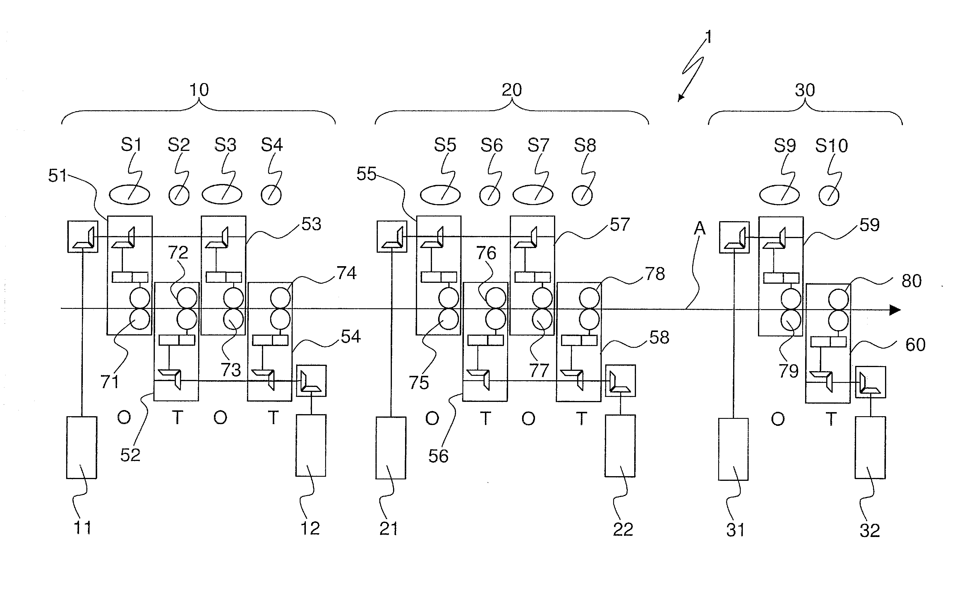
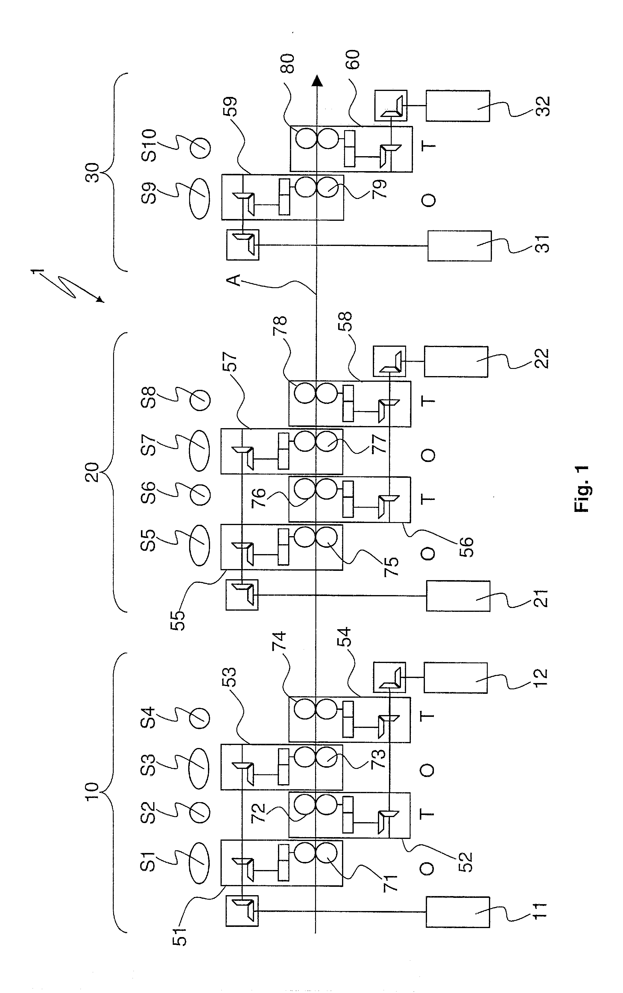
[0033]In particular, FIG. 1 shows a kinematic diagram of the wire rod rolling apparatus 1 according to the invention, hereinafter also defined as finish block or conventionally called wire rod block.

[0034]Three distinct and mutually independent rolling units 10, 20, 30 are provided therein. The first unit 10, considered in the rolling direction, carries out the first four rolling steps, with a rolling sequence in which the gauge section is oval-round-oval-round. Hereinafter, for the sake of brevity, the terms “round or oval” means gauge with round or oval section.

[0035]One motor is provided for actuating the two round steps, arranged in even positions, and one motor, independent from the first, is provided to actuate the two oval steps which occupy the odd positions. The second unit 20 carries out four rolling steps with an oval-round-oval-round rolling sequence. One motor is provided for actuating the two round steps, arranged in even positions, and one motor, independent from the ...


PUM

PropertyMeasurementUnit
temperatureaaaaaaaaaa
powersaaaaaaaaaa

Abstract

A wire rod rolling plant constituted by three distinct, independent rolling units (10, 20, 30), wherein there are provided four rolling stands, arranged in oval-round-oval-round sequence, in the first two rolling units, and there are provided at least two rolling stands, in oval-round sequence, in the third rolling unit. One motor (12, 22) is provided in the first two rolling units (10, 20) for actuating the two round steps arranged in even positions and one motor (11, 21), independent from the first one, is provided for actuating the two oval steps arranged in odd positions. Two motors (31, 32), mutually independent, which actuate each rolling step respectively are provided in the third rolling unit.

Description

FIELD OF THE INVENTION[0001]The present invention relates to a wire rod hot rolling apparatus and method thereof, and in particular is applied to the so-called fast rolling blocks or finish blocks or Wire-Rod-Blocks, arranged downstream of the rolling mill.STATE OF THE ART[0002]Wire rod rolling plants are known, comprising a wire rod block which traditionally consists of a sequence of 8-10 rolling stands with pairs of overhangingly mounted rings having rotation axes mutually and alternatively offset by 90° along the pass-line.[0003]In conventional type blocks, the rolling stands are mechanically restrained to one another by one or more motion transmission shafts which, by means of bevel gear speed shifts, are controlled by a single motor or by several motors connected to one another along a mechanical axis. They are normally synchronous, water-cooled motors, with powers in excess from 2500 kW to over 6000 kW.[0004]The disadvantage of such a situation is that the rolling block is rig...

Claims


Application Information

Patent Timeline
Patent Type & Authority Applications(United States)
IPC IPC(8): B21B13/00
CPCB21B1/18B21B13/005B21B27/024B21B13/00B21B35/04B21B2267/24B21B35/02
Inventor DE LUCA, ANDREANOBILE, MATTEO
Owner DANIELI & C OFF MEC SPA
Why Eureka
Try Eureka