Junction box for LED drivers

a technology of led drivers and junction boxes, which is applied in the direction of casings/cabinets/drawers, casings/cabinets/drawers details, lighting and heating apparatus, etc., can solve the problems of difficult task, non-standard household or commercial alternating current operation of lighting, etc., and achieve the effect of convenient configuration and us

Active Publication Date: 2018-04-24
ELEMENTAL LED
View PDF12 Cites 10 Cited by
  • Summary
  • Abstract
  • Description
  • Claims
  • Application Information

AI Technical Summary

Benefits of technology

[0009]Aspects of the invention relate to junction boxes that are adapted to accept drivers of various sizes and that can be readily configured and used. A junction box according to one embodiment of the invention has a bottom or base. Dividers arising from the base divide the junction box into three compartments: a main compartment, into which a driver may be installed, and two end compartments. A U-shaped cut-out in each of the dividers allows an installer to “drop in” a driver without having to pull its wires through holes, and each of the compartments includes a number of frangible portions that may be punched out to make holes for wires to enter the junction box. Those frangible portions may be provided at the ends and along the sides of the two compartments, which allows the installer to select exactly where he or she wishes the wires to enter the junction box. Hardware mounted to the base is adapted to secure the driver within the junction box, and in many cases, allows an installer to do so without tools. A cover covers and closes the junction box and supplies a top and at least a part of a sidewall of the junction box, leaving the base open along at least one sidewall for ease of driver installation. The cover may, for example, be L-shaped or U-shaped. If the cover is U-shaped, it may define parts of two sidewalls, leaving the base open from two sides during driver installation.
[0012]Yet another aspect of the invention relates to weather-resistant or weather-proof junction boxes. The junction boxes include a bottom or base and a cover. Dividers arising from the base divide the junction box into three compartments: a main compartment, into which a driver may be installed, and two end compartments. A U-shaped cut-out in each of the dividers allows an installer to “drop in” a driver without having to pull its wires through holes, and each of the compartments includes a number of frangible portions that may be punched out to make holes for wires to enter the junction box. Those frangible portions may be provided at the ends and along the sides of the two compartments, which allows the installer to select exactly where he or she wishes the wires to enter the junction box. Hardware mounted to the base is adapted to secure the driver within the junction box, and in many cases, allows an installer to do so without tools. As in other embodiments, the cover generally covers and defines the top and at least a portion of one of the sidewalls of the junction box. The cover also includes depending flaps that extend down over the joint between cover and base. Junction boxes according to these embodiments of the invention typically do not include regular sets of holes or openings for ventilation, but they may include drainage holes or other such openings, so that any water that enters the junction box can readily exit. Other embodiments of weather-resistant junction boxes according to aspects of the invention may use sealing structure, such as a gasket or gaskets, between the base and the cover.
[0013]A further aspect of the present invention relates to junction boxes with reduced internal structure. Junction boxes according to this aspect of the invention typically include a bottom or base and a cover. The base is divided into a main compartment, which would typically carry a driver and its low-voltage wiring, and a high-voltage compartment. The high-voltage compartment is separated from the main compartment by a divider that has a U-shaped cut-out, so that a driver can be “dropped in” without having to pull wires through holes. The cover typically defines the top and at least a portion of at least one sidewall of the junction box, which means that the base is open at the top and along at least a portion of one sidewall during driver installation. In some embodiments, the dividers may be removable.

Problems solved by technology

However, as LED-based lighting has come into wider usage, a number of challenges have arisen.
Chief among those challenges is the fact that most LED lighting does not operate on typical household or commercial alternating current (AC) power.
Since junction boxes are often installed in tight spaces, their installation is not necessarily easy, and the need to painstakingly pull wires through the physical barriers between high- and low-voltage sides of a junction box can make the task much more difficult.

Method used


Image

  • Junction box for LED drivers
  • Junction box for LED drivers
  • Junction box for LED drivers

Examples


Embodiment Construction

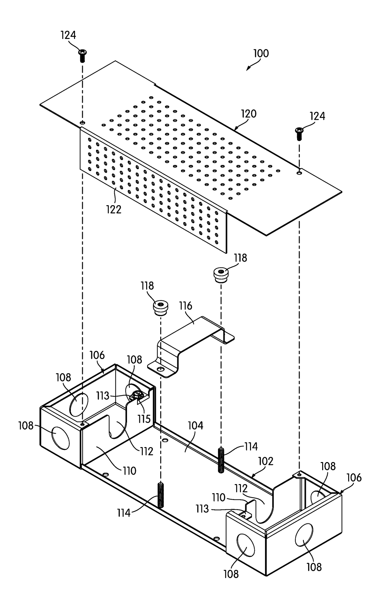
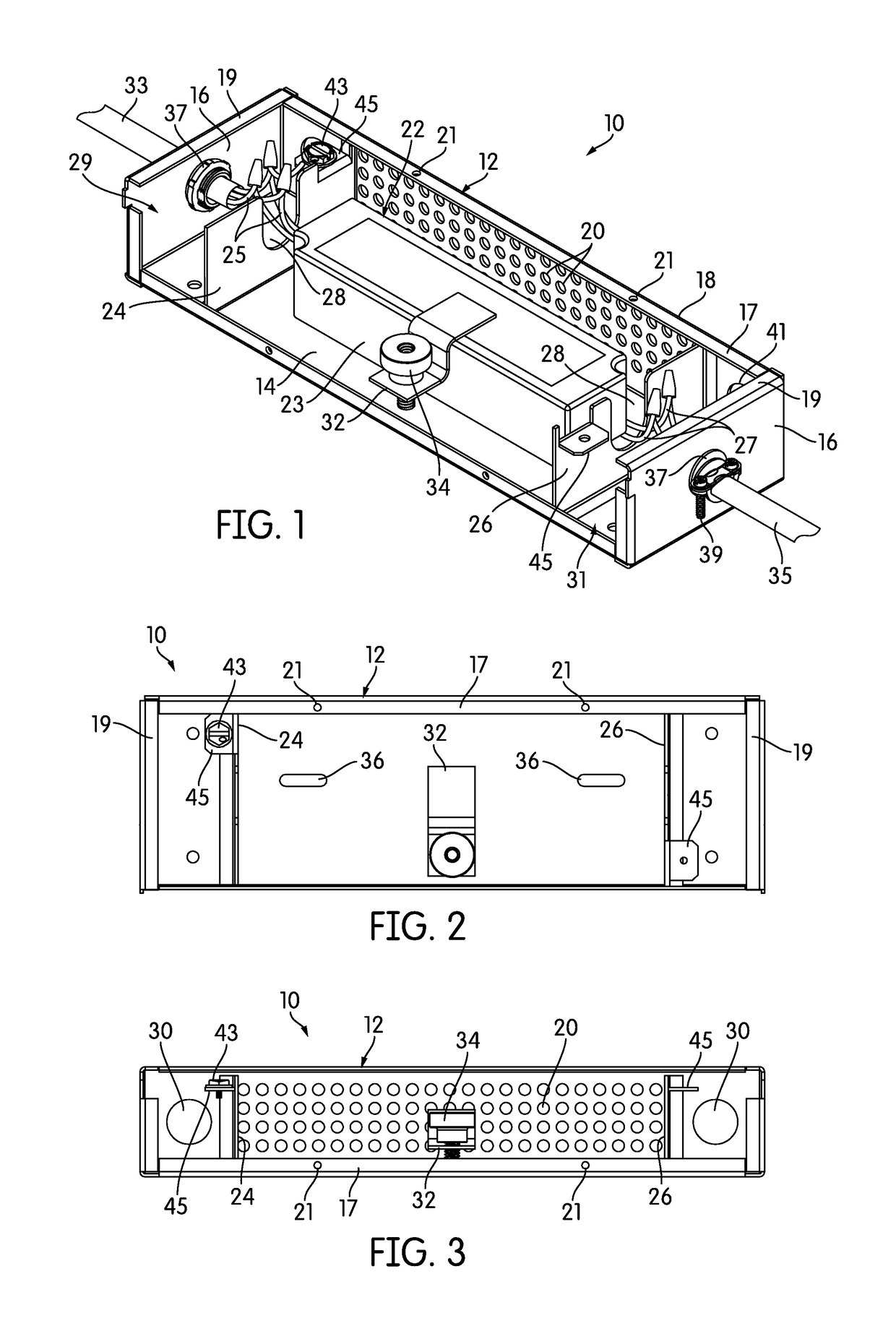
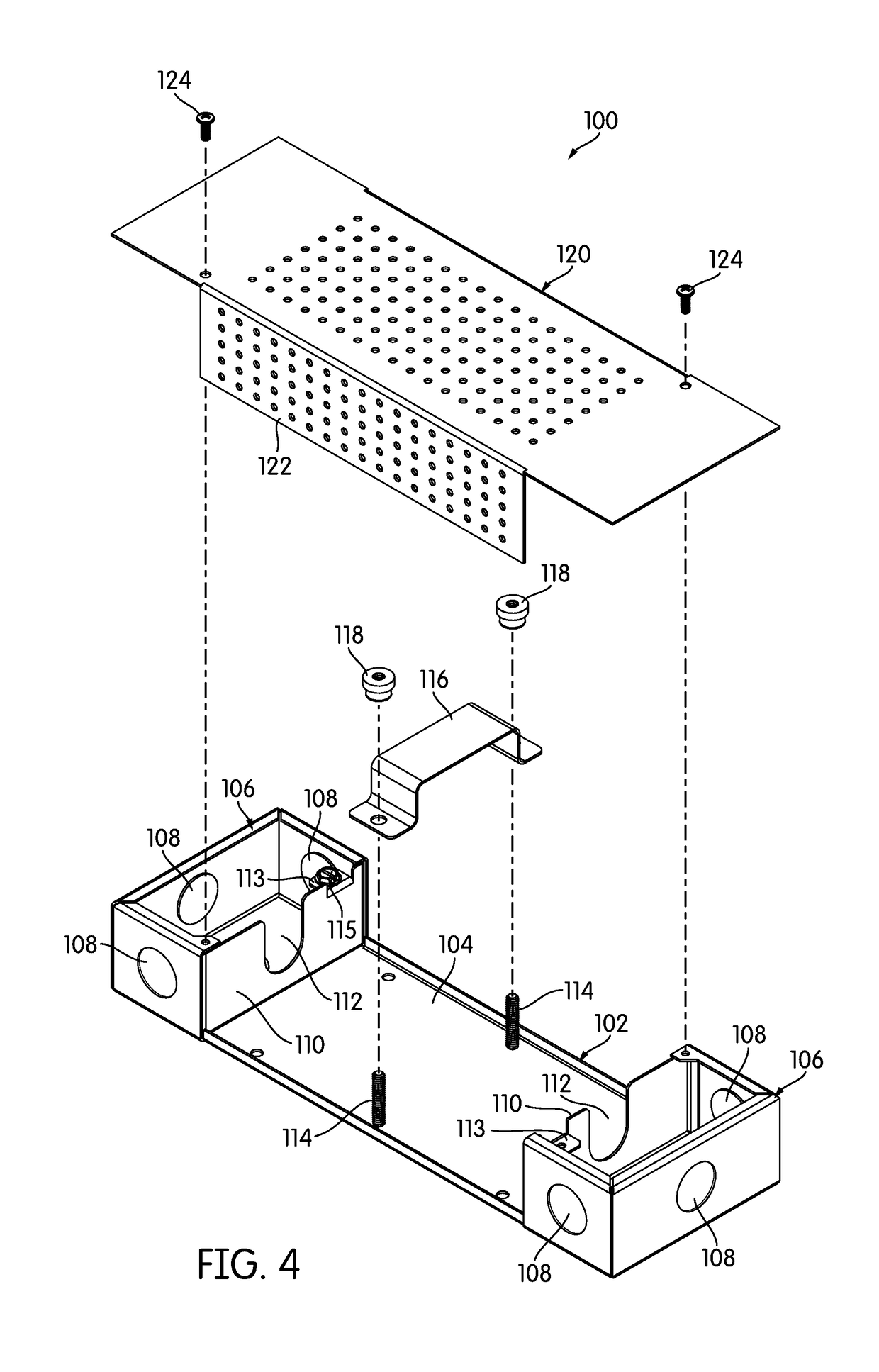
[0039]FIG. 1 is a perspective view of a junction box, generally indicated at 10, according to one embodiment of the invention. The junction box 10 is typically a metal enclosure with a cover. In the illustrated embodiment, a first part 12 of the junction box 10 defines a bottom or base 14. Arising from the base 14 are two end faces 16 and a long, side face 18. The side face 18 of the illustrated embodiment has perforations 20 for ventilation. The first part 12 of the junction box 10 thus provides four faces of what, when assembled, is a six-face rectangular prism. An L-shaped cover (not shown in FIG. 1) provides the remaining faces and closes the junction box 10. Each of the upstanding faces 16, 18 includes bent-over tabs or flanges 17, 19 that include holes 21 for attaching to the cover with fasteners. Of course, other configurations are possible and the cover may be, for example, U-shaped.

[0040]The junction box 10 includes a driver compartment 22 that has ample space to allow the ...


PUM


Abstract

Junction boxes for enclosing and making electrical connections to LED drivers are disclosed. The junction boxes include a bottom or base and a cover. Dividers arising from the base divide the junction box into high-voltage and low-voltage compartments. A cut-out open at the top of each divider allows a driver to be placed in a junction box without having to pull wires through holes or openings. Typically, the base is open along the top and along at least a portion of one sidewall, with the cover being L- or U-shaped to complete the enclosure. Various mounting mechanisms are disclosed for securing drivers within junction boxes. Embodiments that can house several drivers or components within one junction box are disclosed, as are weather- and water-resistant embodiments.

Description

CROSS-REFERENCE TO RELATED APPLICATIONS[0001]This application claims priority to U.S. Provisional Patent Application No. 62 / 309,744, filed Mar. 17, 2016, and to U.S. Provisional Patent Application No. 62 / 436,318, filed Dec. 19, 2016. The contents of both of those applications are incorporated by reference herein in their entirety.BACKGROUND OF THE INVENTION[0002]1. Field of the Invention[0003]The invention relates to junction boxes for making electrical connections, and more particularly, to junction boxes adapted for use with multiple drivers.[0004]2. Description of Related Art[0005]Lighting based on light-emitting diodes (LEDs) has become increasingly popular because of its high efficiency, relatively low cost, and adaptability. However, as LED-based lighting has come into wider usage, a number of challenges have arisen. Chief among those challenges is the fact that most LED lighting does not operate on typical household or commercial alternating current (AC) power. Many LED light...

Claims


Application Information

Patent Timeline
Patent Type & Authority Patents(United States)
IPC IPC(8): H05K5/03F21V23/00H05K5/00F21V29/83F21V31/00F21V17/12H02G15/10F21W131/10F21Y115/10
CPCF21V23/003F21V17/12F21V23/001F21V29/83H02G15/10H05K5/0091H05K5/03F21V31/005F21Y2115/10F21W2131/10H02G3/088
Inventor BUCK, WESLEYPETERSEN, RUSSELL
Owner ELEMENTAL LED
Why Eureka
Try Eureka