Light tower

a technology of light towers and towers, applied in outdoor lighting, searchlight transportation, lighting applications, etc., can solve the problems of mobile light towers toppling, inherent safety risks, etc., and achieve the effect of reducing the risk of toppling, accurate prediction of the effect of the effect of falling, and more sensitive measurements

Active Publication Date: 2018-04-24
HEIMDALL UK LTD
View PDF20 Cites 3 Cited by
  • Summary
  • Abstract
  • Description
  • Claims
  • Application Information

AI Technical Summary

Benefits of technology

[0010]The controller may act to alter / control the load distribution such that the light tower is at reduced risk of toppling. Furthermore, monitoring of a property of the light tower itself, as opposed to monitoring a property of any single external force acting on the light tower, may allow for more sensitive measurements and may allow for a more accurate prediction of the whether the light tower is at risk from toppling.
[0017]The controller may be configured to raise and / or lower the mast, e.g. relative to the main body, when the monitored weight distribution is outside the pre-determined acceptable weight distribution range. Raising and / or lowering the mast may thereby alter the weight distribution of the light tower, allowing the weight distribution to be brought back to a safe weight distribution where there is no risk of toppling.
[0028]The controller may inhibit raising of the mast above its retracted condition until an acceptable load distribution threshold is achieved between the supports. The controller may require that each support bears a predetermined proportion of the weight of the lighting tower, e.g. according to a minimum load value or a minimum proportion of the total load sensed across all supports. This feature may ensure that the mast is established in a safe condition before the mast can be erected and / or used for lighting. This is particularly useful in ensuring the ongoing stability of the mast.
[0031]The controller may be configured to actuate one or more of the plurality of legs when the monitored load distribution is outside the pre-determined range of load distributions, e.g. for longer than a pre-determined period of time. Thus the stability of the light tower may be improved by selectively actuating one or more support, e.g. in response to a change in the load distribution of the tower in use.
[0039]The light tower may comprise means for monitoring characteristics of the forces acting on the mast, and a controller configured to raise and / or lower the mast when the monitored characteristics fall outside a range of pre-determined characteristics. For example, the light tower may comprise means for measuring the angle and / or magnitude and / or acceleration of forces acting on the mast. The light tower may comprise a gyroscope or a wind sensor or the like. In such an embodiment having two alternative means for detecting unsafe operating conditions may allow for earlier and / or more certain detection of unsafe conditions, and may provide for a backup means for detecting unsafe operating conditions where one of the means fails.

Problems solved by technology

Whilst the use of mobile light towers is widespread, conventional mobile light towers can suffer from stability issues, which may cause an inherent safety risk.
In particular, when the mast of a mobile light tower is in an extended position, the mast may be exposed to high winds, which may cause the mobile light tower to topple when the wind is strong enough.
Furthermore, where the mobile light tower is placed in a location where the ground is unstable or uneven, any shift in the ground, or movement of the mobile light tower relative to the ground, may cause the mobile light tower to topple.
The weight of mobile light towers not only provides a safety risk to individuals when it is toppled but also can cause significant damage to the tower itself or adjacent equipment.
The nature of gusting winds means that the tower can become unsafe very quickly, particularly when located on uneven ground.

Method used


Image

  • Light tower
  • Light tower
  • Light tower

Examples


Embodiment Construction

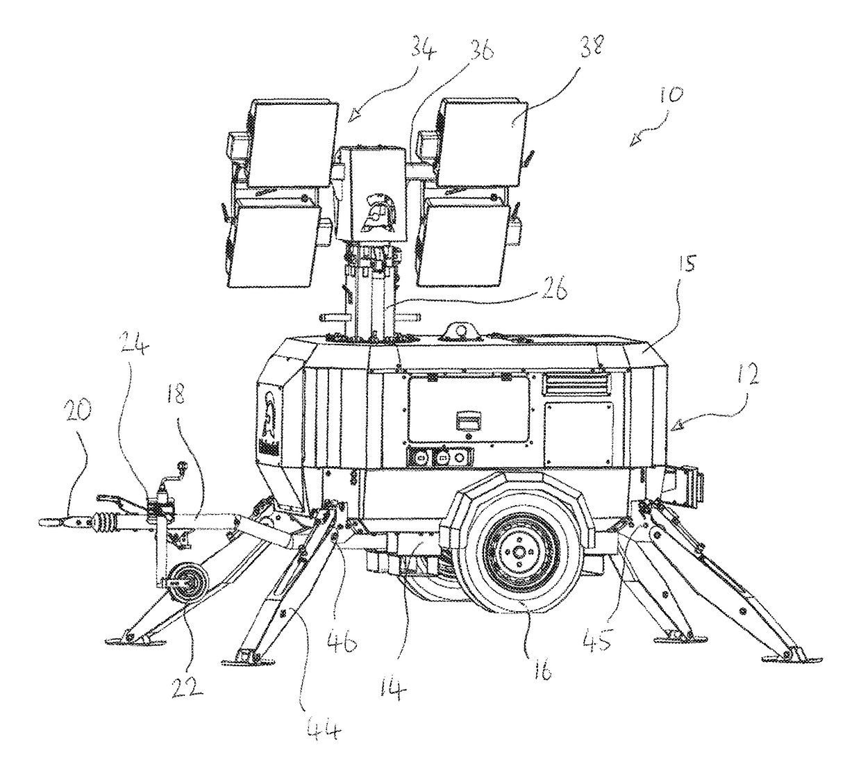
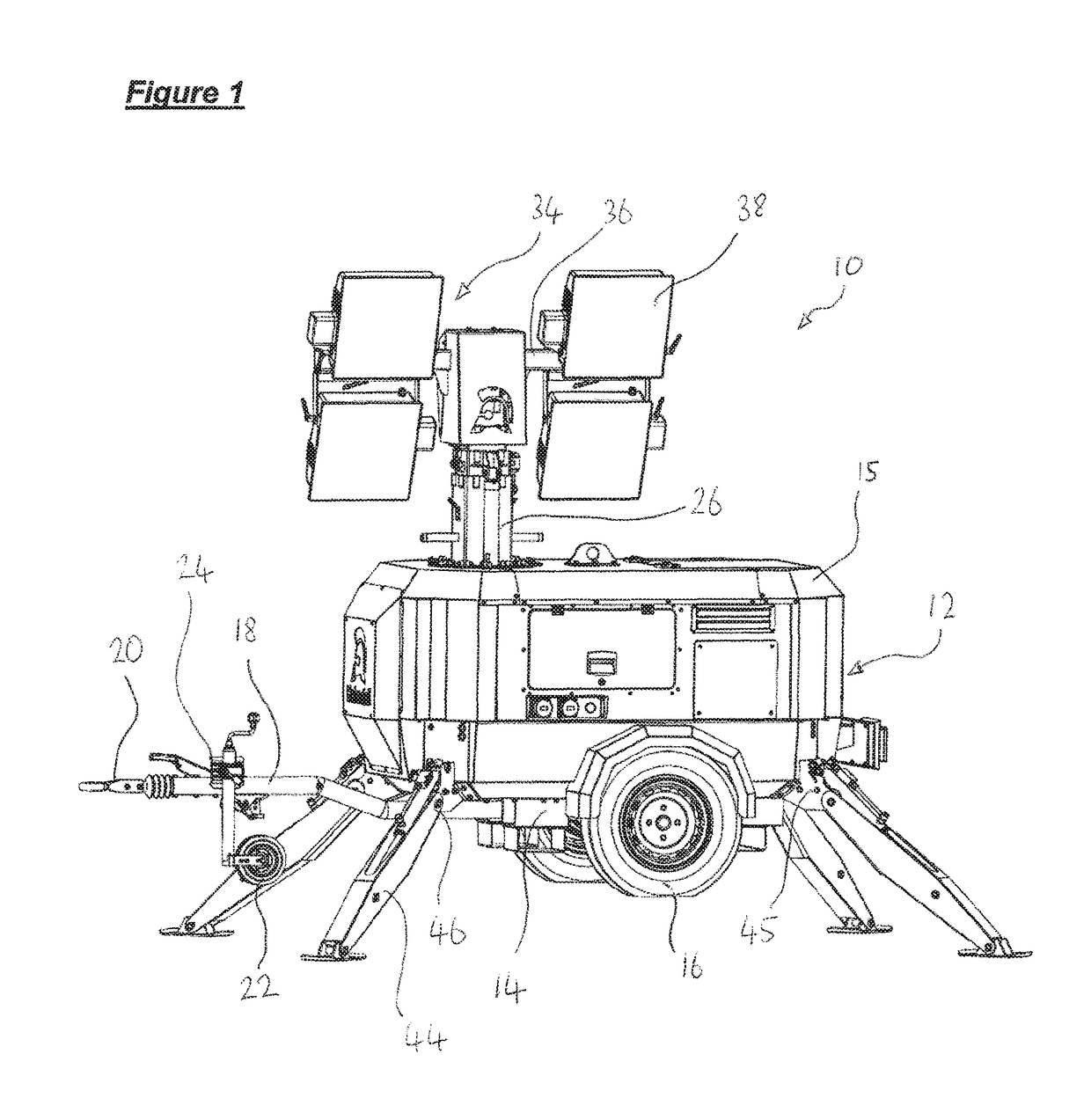
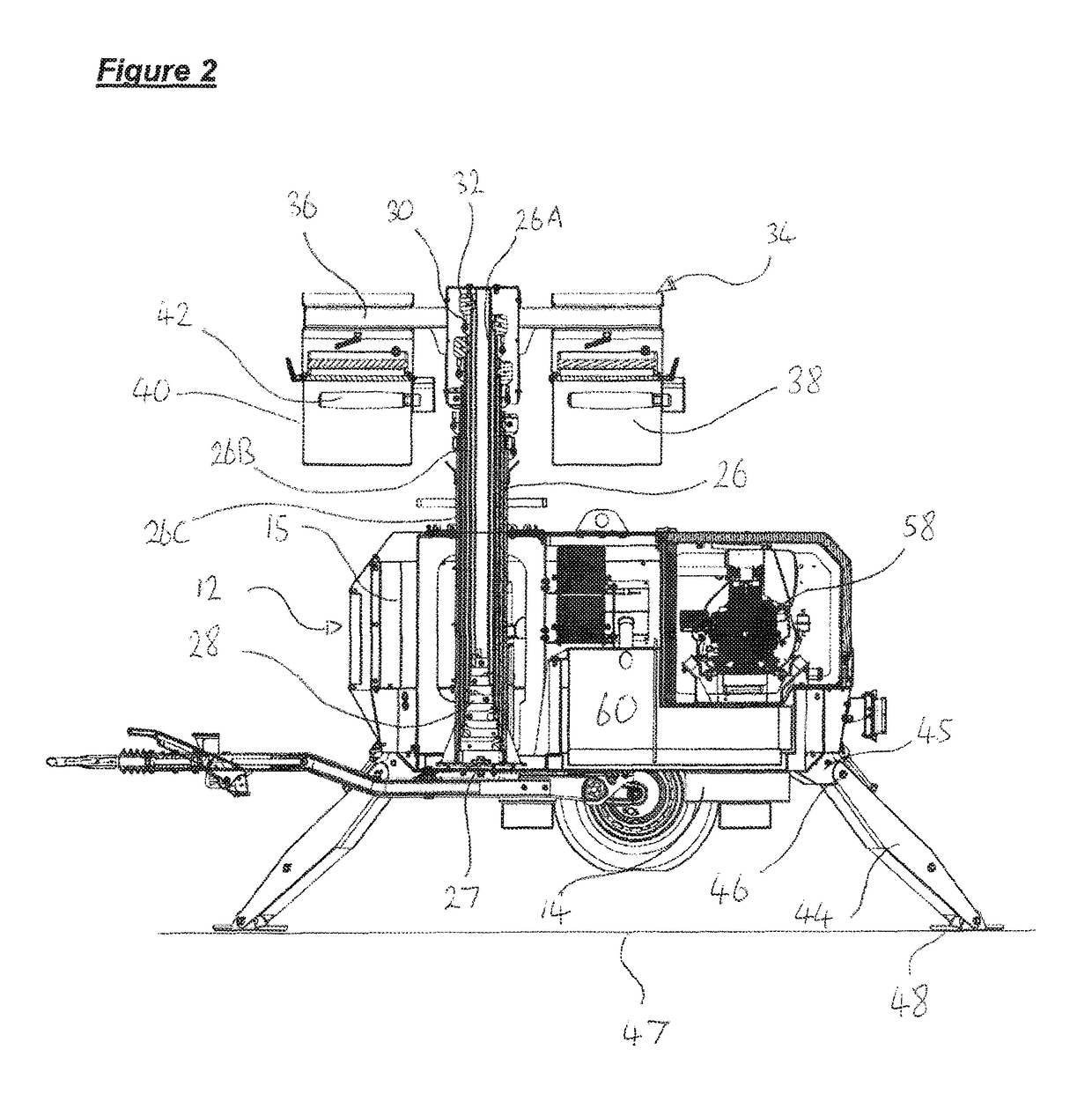
[0049]A mobile lighting tower unit 10 is shown in FIGS. 1 and 2 in a condition ready for use. The lighting tower unit 10 generally comprises a main body 12, which houses the power, actuation and control systems for the lighting tower. The main body 12 comprises a chassis 14 and a casing 15, providing a hollow interior in which the internal systems can be mounted.

[0050]A pair of wheels 16 are mounted to the main body 12, e.g. by an axle supported by the chassis so as to allow the lighting unit 10 to roll on its wheels. A tow arm 18 depends from the chassis 14 and allows for connection to a vehicle at a connector formation 20. A caster / wheel 22 is mounted to the tow arm 18 in a conventional manner and is provided with a manual break 24, although such features may optionally be omitted as necessary.

[0051]A lighting mast 26 is mounted within the main body 12 such that the mast 26 is upstanding from the chassis and / or casing 15. The lower end of the mast 26 is typically mounted to the ch...


PUM


Abstract

This invention concerns a light tower (10) having a main body (12) and a mast (26) extending from the main body (12) such that the mast (26) is extendable between a retracted configuration and at least one extended configuration. A lighting unit (34) is mounted to the mast (26). Supports (44), such as legs, are arranged to support the main body in use. Sensors (56) are provided for monitoring the load distribution of the light tower (10) between the supports (44). A controller (64) is configured to alter the load distribution of the light tower (10) according to a comparison between the monitored load distribution and a predetermined acceptable load distribution range.

Description

BACKGROUND OF THE INVENTION[0001]This disclosure relates to light towers, and more particularly, although not exclusively, to a method and system for controlling the safety / stability of a mobile light tower.[0002]Mobile light towers are typically used to provide lighting at locations where there are no fixed light sources, and are commonly used, for example, on building / work sites, at sporting / entertainment events, or in other remote locations. Conventional mobile light towers comprise a main body, an extendable mast, and a lighting unit disposed at the distal end of the mast. The main body typically houses a power source powering the lighting unit, and wheels which give the tower its mobility. The extendable mast can be used to raise or lower the lighting unit to a desired position such that appropriate lighting of an area can be achieved.[0003]Whilst the use of mobile light towers is widespread, conventional mobile light towers can suffer from stability issues, which may cause an ...

Claims


Application Information

Patent Timeline
Patent Type & Authority Patents(United States)
IPC IPC(8): H05B37/02F21L13/00F21V21/14B62D49/08F21L14/04F21V21/36G01M1/12F21V21/22B60P3/18F21W131/10F21W131/402
CPCH05B37/0227B62D49/08F21L13/00F21L14/04F21V21/145F21V21/36G01M1/12F21V21/22F21W2131/402B60P3/18F21W2131/1005H05B47/105
Inventor FLETCHER, CHRISTOPHER DAVID
Owner HEIMDALL UK LTD
Why Eureka
Try Eureka