
Planning an implantation of a cardiac implant

a cardiac implant and imaging system technology, applied in the direction of catheters, instruments, image enhancement, etc., can solve the problems of inability to achieve the effect of reducing the risk of cardiac surgery, affecting the survival of patients,

Active Publication Date: 2018-05-01
KONINKLJIJKE PHILIPS NV
View PDF10 Cites 4 Cited by
  • Summary
  • Abstract
  • Description
  • Claims
  • Application Information

AI Technical Summary

Benefits of technology

[0040]In contrast to most of the prior art planning systems of this kind, not only one cardiac image but a plurality of such 3D cardiac images are used for the simulation and evaluation. The term “a plurality” shall be understood in the context of the present invention as “at least two”. This has a couple of advantages: First, it is tedious to check a series of images for identifying the most relevant image for planning the implantation of the cardiac implant. A doctor or a medical assistant usually has to manually find a suitable image which may be quite time-consuming. Secondly, by evaluating a plurality of 3D cardiac images showing different conditions of the heart during the cardiac cycle, possible unwanted collisions between the cardiac implant and parts of the heart that move during the cardiac cycle may be estimated in a much more precise manner. Depending on the heart movement, the cardiac implant may interfere with one heart region in a first image, but may not interfere with said region of the heart when considering it in another image. Using a plurality of 3D cardiac images for the planning procedure therefore allows to more precisely determining the implant position, the size and shape of the cardiac implant.
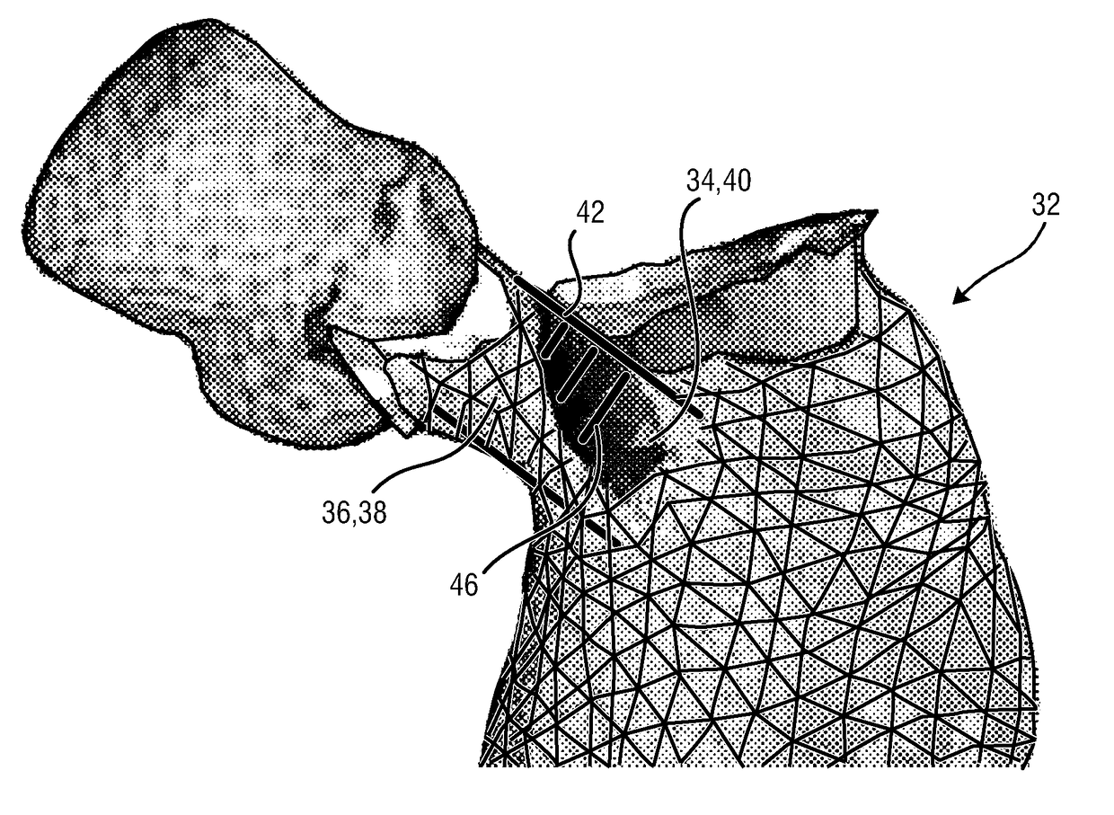
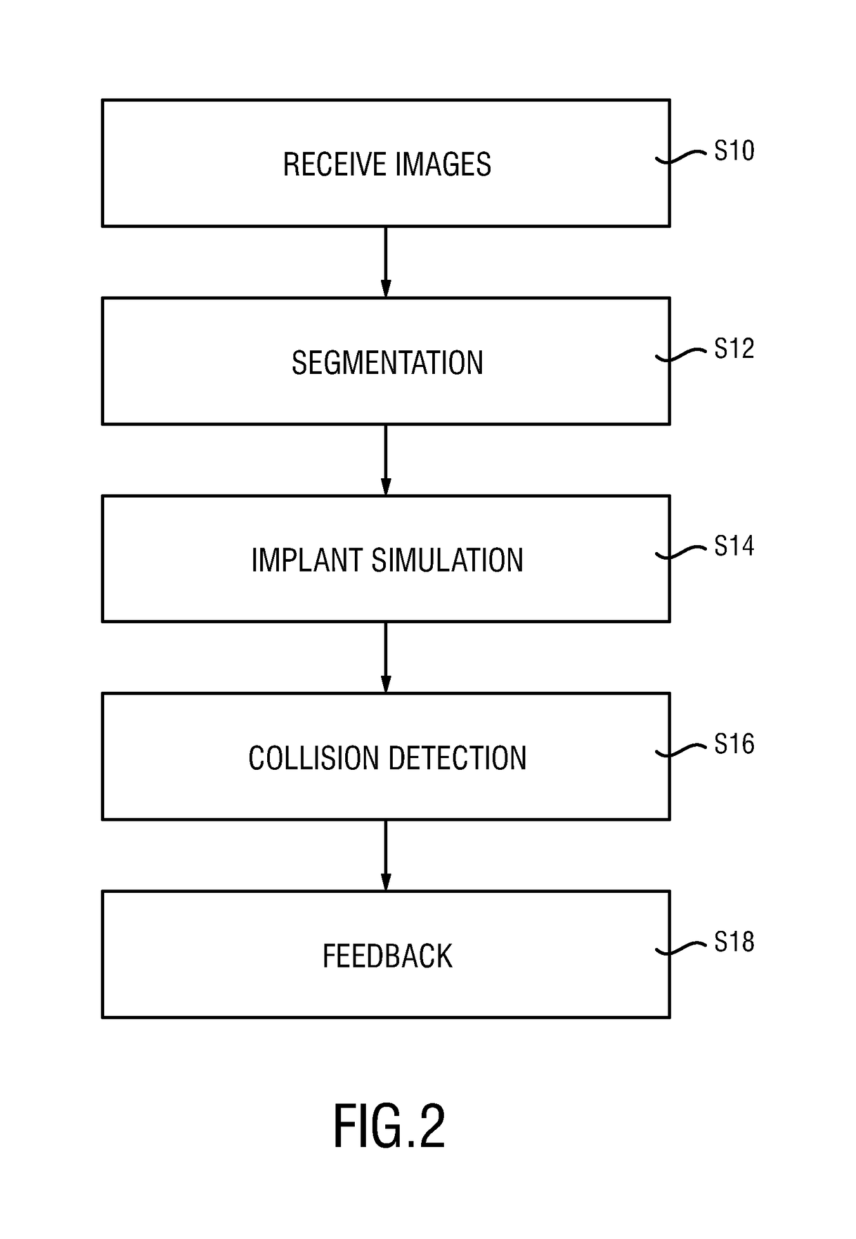
[0043]A further characteristic of the present invention is the simulation of the cardiac implant within the target implant region. Preferably, a simple geometrical model may be used to simulate the cardiac implant. This simulated cardiac implant may be used to evaluate an overlap with the locally adjacent region that has been segmented prior thereto. A feedback unit, which may e.g. be realized by a display, then provides feedback information concerning the evaluated overlap to a physician or medical staff. The overlap may e.g. be displayed for all evaluated cardiac images. This direct feedback concerning possible collisions of the cardiac implant with parts of the heart based on a plurality of 3D cardiac images is a very powerful tool during planning of such a cardiac implantation.
[0053]Referring back to the TAVI example, it has been shown that these location-dependent maximum overlaps between the anterior mitral leaflet movement and the prolongation of the left ventricular outflow tract vary considerably between different patients. Such an aggregated maximum overlap evaluation could therefore be a good indicator for risk of friction between the mitral valve leaflet and the TAVI implant. It has also been shown that for some patients the absolute maximum overlap (maximum overlap value of all found relative maxima) occurs closer to the aortic valve than for others. The above-mentioned graphical representation may therefore help a physician to identify patient-individual risk zones.
[0056]According to a further embodiment, the system may additionally comprise an input interface that allows a user to vary a size, a shape and / or a position of the simulated cardiac implant.

Problems solved by technology

This is, however, a very invasive and expensive treatment.
In addition, it is considered too high risks or contraindicated for many patients.
Although TAVI is less invasive, its long-term outcome is unclear.
If the TAVI implant is placed too low, i.e. reaching too far into the left ventricular outflow tract, it can impair movement of the anterior mitral leaflet.
Case reports demonstrated that contact between the implant and the mitral valve leaflet led to mitral endocarditis and leaflet aneurysms, see e.g. Piazza, N. et al.
First, repetitive friction between the implant and the leaflet could damage the leaflet surface.

Method used


Image

  • Planning an implantation of a cardiac implant
  • Planning an implantation of a cardiac implant
  • Planning an implantation of a cardiac implant

Examples


Embodiment Construction

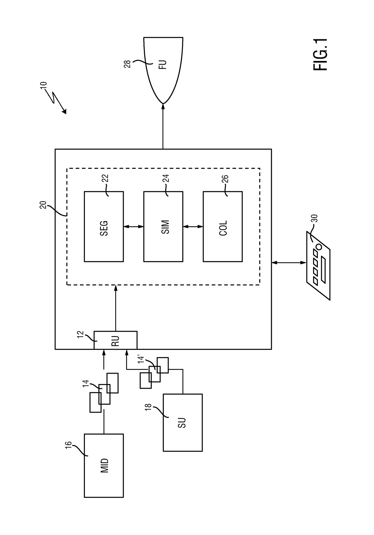
[0070]FIG. 1 shows a simplified and schematic block diagram to illustrate the principal components of the presented medical imaging system, which may be particularly used for planning an implantation of a cardiac implant. The medical imaging system is therein in its entirety denoted with reference numeral 10.

[0071]It comprises a receiving unit (RU) 12 which is configured to receive a plurality of 3D cardiac images 14. Said plurality of 3D cardiac images 14 is preferably a sequence of timely consecutive frames that are acquired with a medical imaging device (MID) 16. This medical imaging device 16 may be a volumetric CT scanner, an MRI scanner or a 3D ultrasound system. A particular example of a 3D ultrasound system which may be applied for the system of the current invention is the iE33 ultrasound system sold by the applicant, in particular together with an X7-2 t TEE transducer of the applicant or another 3D transducer using the xMatrix technology of the applicant. Even though the ...


PUM


Abstract

The present invention relates to a medical imaging system (10) for planning an implantation of a cardiac implant (42), comprising: a receiving unit (12) for receiving a plurality of three-dimensional (3D) cardiac images (14, 14′) showing different conditions of a heart (32) during a cardiac cycle; a segmentation unit (22) for segmenting within the plurality of 3D cardiac images (14, 14′) a target implant region (38) and a locally adjacent region (40) that could interfere with the cardiac implant (42); a simulation unit (24) for simulating the implantation of the cardiac implant (42) within the target implant region (40) in at least two of the plurality of 3D cardiac images (14, 14′); a collision evaluation unit (26) for evaluating an overlap (46) of the simulated cardiac implant (42) with the segmented locally adjacent region (40) in at least two of the plurality of 3D cardiac images (14, 14′); and a feedback unit (28) for providing feedback information to a user concerning the evaluated overlap (46).

Description

[0001]This application is the U.S. National Phase application under 35 U.S.C. § 371 of International Application No. PCT / EP2014 / 061254, filed on May 30, 2014, which claims the benefit of EP Application No. 13170984.2 filed on Jun. 7, 2013. These applications are hereby incorporated by reference herein.FIELD OF THE INVENTION[0002]The present invention relates to a medical imaging system for planning an implantation of a cardiac implant. Furthermore, the present invention relates to a corresponding method for planning an implantation of a cardiac implant. It also relates to a computer program comprising program code means for causing a computer to carry out the steps of said method. An exemplary technical application of the present invention is the planning of a transcatheter aortic valve implantation (TAVI) for treating aortic stenosis.BACKGROUND OF THE INVENTION[0003]Valvular heart diseases are among the most prominent causes of heart failure and premature cardiac death. Aortic valv...

Claims


Application Information

Patent Timeline
Patent Type & Authority Patents(United States)
IPC IPC(8): A61B34/10G06T7/246G06T7/174G06T7/33A61B8/12A61B8/08G06T7/00G06T19/00
CPCA61B34/10A61B8/12G06T7/0016G06T7/174G06T7/251G06T7/33G06T19/00A61B8/0883G06T2210/41A61B2034/104A61B2034/107G06T2207/10136G06T2207/30048G06T2207/30052G06T2207/30241G06T2210/21
Inventor WEBER, FRANK MICHAELSTEHLE, THOMAS HEIKOWACHTER-STEHLE, IRINAPETERS, JOCHENWEESE, JUERGEN
Owner KONINKLJIJKE PHILIPS NV
Learn More