System, program and method where wireless terminal discovers access point

a wireless terminal and access point technology, applied in the field of communication sequence technology, can solve the problems of consuming more electric power of the wireless terminal, requiring a comparatively long waiting time for the beacon to be received, and the active scan method achieving a comparatively short waiting time for the response of the probe, so as to achieve a small amount of consumption energy and short waiting time

Active Publication Date: 2018-05-01
KDDI CORP
View PDF19 Cites 1 Cited by
  • Summary
  • Abstract
  • Description
  • Claims
  • Application Information

AI Technical Summary

Benefits of technology

The invention described in this patent allows a wireless device to quickly and easily find a nearby access point with minimal energy usage.

Problems solved by technology

During such frame-broadcasting, the wireless terminal 2 may consume more electric power.
As explained above, the active scan method realizes a comparatively short waiting time for receiving probe responses though requiring a temporal increase in power consumption when sending the probe request.
On the other hand, the passive scan method needs a comparatively long waiting time for receiving beacons although not requiring so much electric power.
Therefore, wireless terminals generally adopt the “active scan method” that consumes comparatively small power and discovers an access point in a comparatively short time.

Method used


Image

  • System, program and method where wireless terminal discovers access point
  • System, program and method where wireless terminal discovers access point
  • System, program and method where wireless terminal discovers access point

Examples


first embodiment

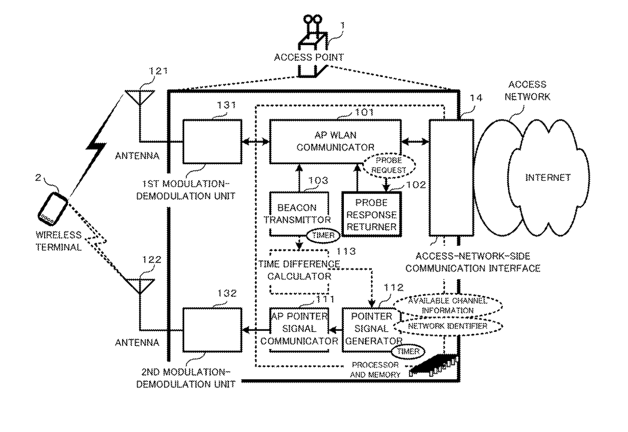
[0082]FIG. 5 is a functional block diagram illustrating an access point according to the present invention.

[0083]The access point 1 is constructed to include, as hardware, two antennas 121 and 122 that communicate with wireless terminal(s) 2, the first modulation-demodulation unit 131 connected with the antenna 121, the second modulation-demodulation unit 132 connected with the antenna 122, and an access-network-side communication interface 14. The antenna 121 and the first modulation-demodulation unit 131 support the communication in the first frequency band, being based on a communication method prescribed in the IEEE802.11 at least. While, the antenna 122 and the second modulation-demodulation unit 132 support the communication in the second frequency band, whether or not being based on a communication method prescribed in the IEEE802.11. Note that the first modulation-demodulation unit 131 and the second modulation-demodulation unit 132 may share a single antenna, utilizing each...

second embodiment

[0091]FIG. 6 is a functional block diagram illustrating an access point according to the present invention.

[0092]According to FIG. 6, an access point 1 uses two frequency bands in a WLAN unlike the access point shown in FIG. 5. The first frequency band is a 5 GHz band (or 2.4 GHz) band prescribed in the IEEE802.11 standard, and the second frequency hand is a 2.4 GHz band (or 5 GHz) hand prescribed in the IEEE802.11 standard. Therefore, transmitting a pointer signal does not require any use of another radio carrier. As shown in FIG. 6, the pointer signal generator 112 transmits a pointer signal to wireless terminal(s) 2 through the second AP WLAN communicator. Of course, the pointer signal generator 112 may transmit a pointer signal to wireless terminal(s) 2 by using another communication method for transmitting and receiving user data.

[0093]In a WLAN, Generally, there is much use of the 2.4 GHz band, in which access points and wireless terminals interfere much with one another. Ther...


PUM


Abstract

A system, a program and a method allow a wireless terminal to discover an objective access point with a comparatively small amount of consumption energy and in a comparatively short waiting time. The access point (AP) includes: an AP WLAN communicator communicating using a predetermined available channel of a first frequency band; a pointer signal generator generating a pointer signal including available-channel information in the first frequency band and a network identifier; and an AP pointer signal communicator using a specific channel of a second frequency band to send the pointer signal to the wireless terminal. While, the wireless terminal receives the pointer signal through the specific channel and controls, in response to the available channel information and network identifier included in the pointer signal, for waiting for receiving a beacon or a probe response transmitted in the first frequency band from the objective access point.

Description

TECHNICAL FIELD[0001]The present invention relates to technology of communication sequences in wireless LAN (WLAN, Wireless Local Area Network) where a wireless terminal discovers an access point to be connected.[0002]This application claims the benefit of priority under the Paris Convention frets Japanese patent application No. 2013-108475, filed on May 23, 2013, which is incorporated herein by reference in accordance with PCT rule 20.6.BACKGROUND ART[0003]FIG. 1 is a schematic diagram showing the configuration of a system including a wireless terminal and access points.[0004]According to FIG. 1, access points 1 are connected to the Internet through access networks while they communicate with a wireless terminal 2 through the air. A wireless terminal 2 staying in an area of WLAN configured around an access point 1 is allowed to be connected to the Internet (a host network) via the access point 1. The wireless terminal 2 shown, in FIG. 1 is in a position where the terminal can commu...

Claims


Application Information

Patent Timeline
Patent Type & Authority Patents(United States)
IPC IPC(8): H04W48/16H04W84/12
CPCH04W48/16H04W76/10H04W84/12Y02D30/70
Inventor YUNOKI, KATSUO
Owner KDDI CORP
Why Eureka
Try Eureka