Metal plate forming method and forming device

a metal plate and forming method technology, applied in the direction of collectors/separators, fuel cell details, other domestic articles, etc., can solve the problems of warpage or undulation, easy to occur in formed articles, large extension of the perimeter inside the material, etc., to reduce the arrangement pitch of the forming tool and restrain warpage or undulation

Active Publication Date: 2018-05-08
TOYOTA BOSHOKU KK
View PDF41 Cites 1 Cited by
  • Summary
  • Abstract
  • Description
  • Claims
  • Application Information

AI Technical Summary

Benefits of technology

[0012]An object of the present invention is to provide a method for forming a metal plate material that is capable of forming protruding portions while restraining warpage or undulation from occurring in the metal plate material.
[0015]There is a case in which the material of a protruding portion extends along a perimeter when the protruding portion is formed by being pressed and flattened by a forming tool in a post-process. In that respect, according to this forming method, it is possible to correct extension along the perimeter of the material of the protruding portion by reducing the arrangement pitch of the forming tool. Therefore, it is possible to restrain warpage or undulation that is generated by forming the protruding portion.

Problems solved by technology

However, when the protruding portions are formed, differences in extension of the material exist partially, and therefore warpage or undulation easily occurs in a formed article.
Particularly when protruding portions are formed by pressing and flattening a metallic material, the extension of the perimeter inside the material becomes large, and warpage or undulation is liable to occur.
Therefore, there is also a difference in residual stress between the front and back of the separator, and warpage or undulation is liable to occur in the separator.
However, the separator disclosed by Patent Document 1 has difficulty in forming a fine impression.
Additionally, the possibility that fatigue failure will occur becomes high because of the impression acting as the starting point of a crack.
Additionally, there is a fear that other warpage will occur simultaneously with the forming of the rib.
Therefore, extension in the perimeter concentrates at the center of the metal plate material, and undulation is liable to occur.
However, according to this method, extension also occurs near the center of the metal plate material having the protruding portions as a result of pulling and lengthening the peripheral part.
Additionally, residual stress occurs in the peripheral part of the metal plate material, and therefore warpage is also liable to occur.

Method used


Image

  • Metal plate forming method and forming device
  • Metal plate forming method and forming device
  • Metal plate forming method and forming device

Examples


Embodiment Construction

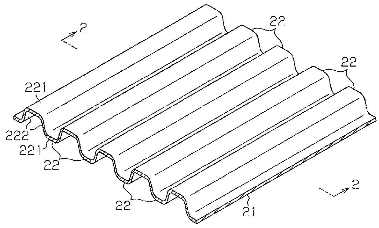
[0025]Referring to FIG. 1 to FIG. 9, a description will be hereinafter given of an embodiment in which a method for forming a metal plate material according to the present invention is employed to manufacture fuel cell separators.

[0026]As shown in FIG. 1 and FIG. 2, a plurality of protruding portions 22 is formed on both sides of a metal plate material 21 that is made into a fuel cell separator. The protruding portions 22 are formed to be evenly spaced in a pleated shape. A material excellent in corrosion resistance, such as titanium, titanium alloys, or stainless steel, is used as the metal plate material 21. In the present embodiment, titanium is used.

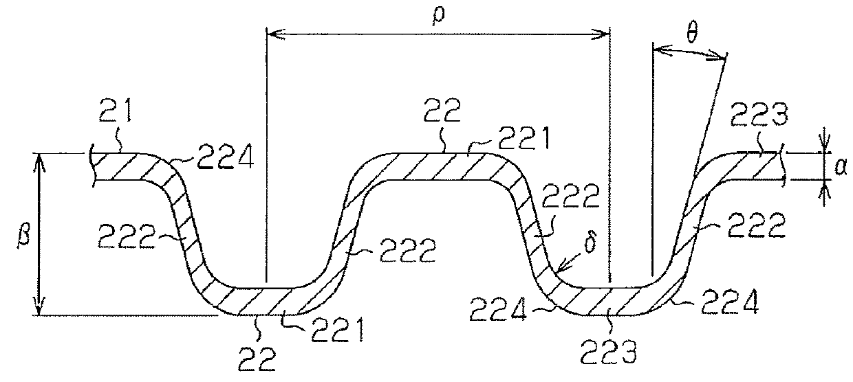
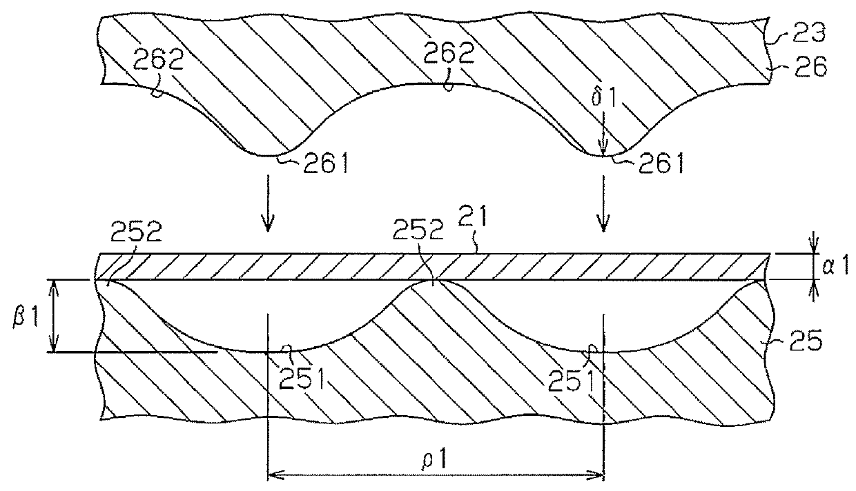
[0027]As shown in FIG. 3, the thickness al of the flat metal plate material 21 that has not yet been formed is uniform as a whole. The thickness al falls within the range of from 0.06 to 0.20 mm, and, in the present embodiment, it is 0.10 mm. As shown in FIG. 2, the thickness α of the metal plate material 21 that has been formed is u...


PUM

PropertyMeasurementUnit
thicknessaaaaaaaaaa
thicknessaaaaaaaaaa
thicknessaaaaaaaaaa

Abstract

A plurality of protruding portions is formed in a metal plate material through a plurality of steps by use of forming tools each of which includes a die and a punch. An arrangement pitch between a concave portion and a convex portion for use in forming the protruding portions in the die and the punch that are used in a post-process is made narrower than an arrangement pitch between a concave portion and a convex portion for use in forming the protruding portions in the die and the punch that are used in a pre-process.

Description

FIELD OF THE INVENTION[0001]The present invention relates to a method for and a device for forming a metal plate material in which the metal plate material is formed to have protruding portions by use of forming tools each of which has a die and a punch.BACKGROUND OF THE INVENTION[0002]A plurality of pleat-shaped protruding portions is formed in a metal plate material forming a fuel cell separator. A flow passage through which a gas, such as hydrogen or oxygen, or processed water flows is formed between adjoining protruding portions. Typically, protruding portions are formed by press forming by use of a forming tool that has a die and a punch when a fuel cell separator is manufactured. However, when the protruding portions are formed, differences in extension of the material exist partially, and therefore warpage or undulation easily occurs in a formed article. Particularly when protruding portions are formed by pressing and flattening a metallic material, the extension of the perim...

Claims


Application Information

Patent Timeline
Patent Type & Authority Patents(United States)
IPC IPC(8): B21D22/02B21D13/02H01M8/0206B21K23/00
CPCB21D22/02H01M8/0206B21K23/00B21D13/02Y02E60/50
Inventor HIRATA, KAZUYUKI
Owner TOYOTA BOSHOKU KK
Why Eureka
Try Eureka