Wheel for center pivot irrigation system

Active Publication Date: 2018-05-08
COVEY DUSTIN
View PDF11 Cites 2 Cited by
  • Summary
  • Abstract
  • Description
  • Claims
  • Application Information

AI Technical Summary

Benefits of technology

The cylindrical design of the preferred steel rim in this invention provides a high level of wheel floatation contact surface, which is much larger than that of conventional rubber center pivot irrigation wheels and tires. The wheel's treads maximize ground contact and floatation for moving center pivot rigs across wet and muddy surfaces. The wheel has also been designed with channels to facilitate easy cleaning in case of mud accumulations.

Problems solved by technology

Rubber tires or wheels which are commonly mounted at the bases of the “A” frame towers of common center pivot agricultural irrigation systems often undesirably slip and incur traction failures within muddy ground surfaces.
Such rubber wheels often further undesirably accumulate compacted mud and debris at and about the tire's peripheral edge and tread, and within the wheel's central hub spaces.

Method used


Image

  • Wheel for center pivot irrigation system
  • Wheel for center pivot irrigation system
  • Wheel for center pivot irrigation system

Examples


Embodiment Construction

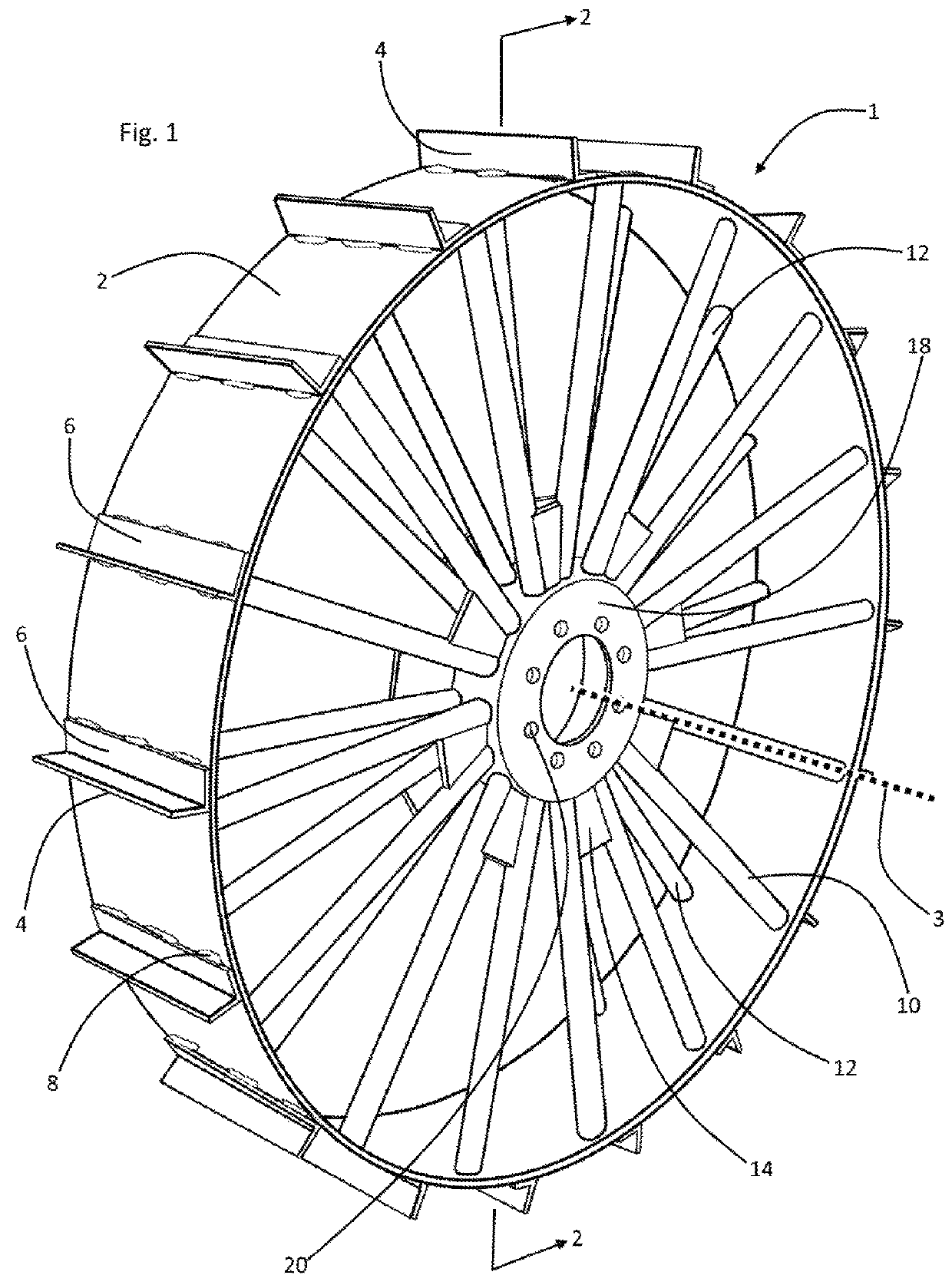
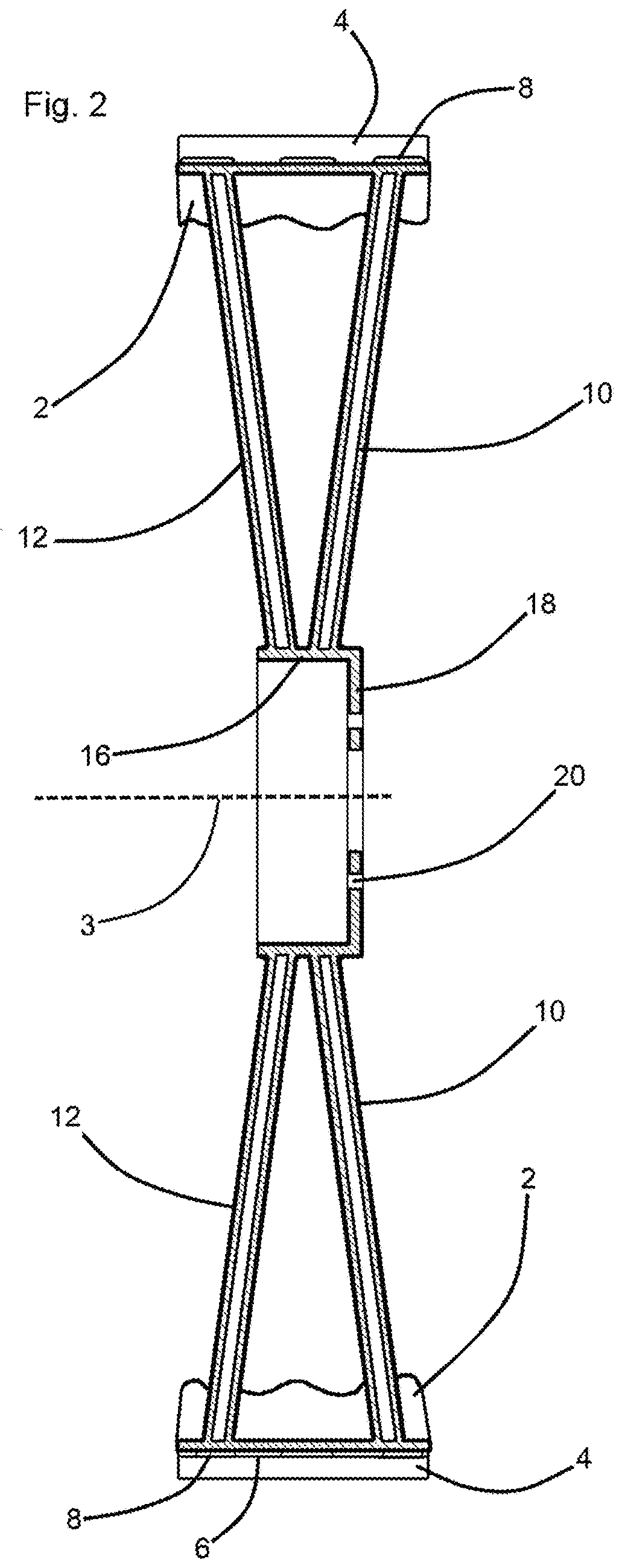
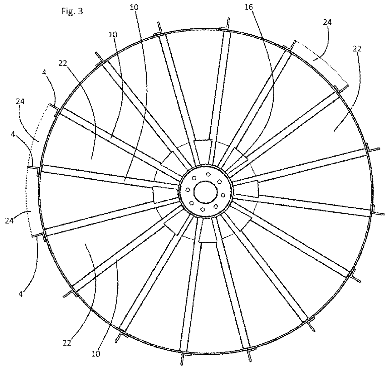
[0019]Referring now to Drawing FIG. 1, a preferred embodiment of the instant inventive center pivot irrigation system wheel is referred to generally by Reference Arrow 1. A central or axially positioned structure of the inventive wheel 1 comprises a wheel hub mounting disc 18, such disc preferably having a radial array of lug receiving apertures 20 and a central wheel hub access aperture 19. An annular spoke mounting flange 16 is preferably fixedly mounted to or formed wholly with disc 18 to form an oppositely laterally opening hub receiving concavity 15.

[0020]A plurality of spoke pairs 10,12 are provided, each spoke pair comprising a lateral spoke 10 and an oppositely lateral spoke 12. A proximal end of each such spoke is preferably fixedly attached by means of welding to the radially outer surface of flange 16, and such spoke pairs are preferably arranged to include or lie within axially extending planes of orientation which intersect at the rotation axis 3.

[0021]In the example of...


PUM


Abstract

A center pivot irrigation system wheel including a hub having an axis of rotation and having lateral and oppositely lateral sides; a plurality of spoke pairs having distal ends and having proximal ends, each proximal end being attached to the hub, each spoke pair having lateral and oppositely lateral spokes, each lateral spoke being intersected by an axially extending plane of orientation, and said each oppositely lateral spoke being intersected by the same plane of orientation; a first plurality of axially extending through spaces, each through space being bounded by an adjacent pair of the spoke pairs; an annular rim having an outer surface, the distal end of each spoke being fixedly attached to the rim; and a plurality of treads, each tread being fixedly attached to the annular rim's outer surface.

Description

CLAIM OF PRIORITY FROM PREVIOUSLY FILED PROVISIONAL PATENT APPLICATION[0001]This non-provisional patent application claims the benefit of and priority from U.S. provisional patent application No. 62 / 139,396 filed Mar. 27, 2015. The inventor disclosed in and applicant of said provisional application are the same. The Specification and Drawings which follow are substantially identical to those presented upon the filing of said provisional application.FIELD OF THE INVENTION[0002]This invention relates to center pivot overhead sprinkler irrigation systems and assemblies of the type incorporating a series of radially extending pipe segments supported by overhead trusses, and further supported by a series of wheeled “A” frame towers. This invention more particularly pertains to the wheels incorporated within such irrigation systems.BACKGROUND OF THE INVENTION[0003]Rubber tires or wheels which are commonly mounted at the bases of the “A” frame towers of common center pivot agricultural irr...

Claims


Application Information

Patent Timeline
IPC IPC(8): B60B1/06B60B15/00A01G25/09
CPCB60B1/06A01G25/092B60B15/00B60B15/023B60B19/12
Inventor COVEY, DUSTIN
Owner COVEY DUSTIN
Why Eureka
Try Eureka