Methods and systems for improving the operation of transmissions for motor vehicles

a transmission and motor vehicle technology, applied in the field of automotive vehicle modification and improvement, can solve the problems of excessive converter pressure entering a separate circuit, loss of converter charge pressure, damage to overheating torque converter, etc., to reduce spring wear, reduce compressive force, and severe overheating

Active Publication Date: 2018-05-15
TRANSGO LLC
View PDF40 Cites 4 Cited by
  • Summary
  • Abstract
  • Description
  • Claims
  • Application Information

AI Technical Summary

Benefits of technology

[0006]The primary object of the present invention is to protect the torque converter of a “factory installed” automotive transmission from damage resulting from over-pressurization. A hydraulic circuit of the automotive transmission is coupled to a converter charge circuit. When pressure exceeds a predetermined value established by a torque converter limit valve in the hydraulic circuit, a valve strokes towards a check valve spring to compress the spring and open the valve, resulting in venting of excessive converter pressure into a separate circuit coupled to pump suction. Over time, normal converter check valve activity weakens the check valve spring, causing it to malfunction or prematurely rupture, resulting in loss of converter charge pressure, resulting in severe and damaging overheating of the torque converter.
[0007]In accordance with the present invention, a spacer element is arranged to act on the valve element to limit the valve stroke, thereby limiting the compressive forces applied to the spring as the valve moves into an open position. The spacer element, by limiting the compressive forces applied to the check valve spring, reduce the wear on the spring, thereby preventing premature breakage of the spring and preventing loss of converter charge pressure which would otherwise result in severe overheating of the torque converter.
[0008]It is also within the scope of the present invention to limit movement of the valve element as the valve element moves into a closed position to limit the expansive forces applied to the spring.

Problems solved by technology

When pressure exceeds a predetermined value established by a torque converter limit valve in the hydraulic circuit, a valve strokes towards a check valve spring to compress the spring and open the valve, resulting in venting of excessive converter pressure into a separate circuit coupled to pump suction.
Over time, normal converter check valve activity weakens the check valve spring, causing it to malfunction or prematurely rupture, resulting in loss of converter charge pressure, resulting in severe and damaging overheating of the torque converter.

Method used


Image

  • Methods and systems for improving the operation of transmissions for motor vehicles
  • Methods and systems for improving the operation of transmissions for motor vehicles
  • Methods and systems for improving the operation of transmissions for motor vehicles

Examples


Embodiment Construction

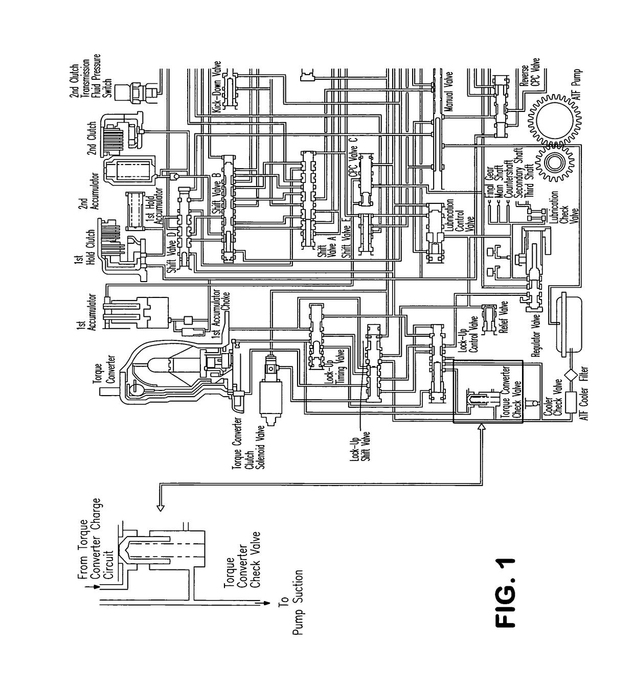
[0013]FIG. 1 of the drawing illustrates a portion of the overall hydraulic circuitry of a “factory installed” automotive transmission for a 4 and 5 speed 98-04 Honda Odyssey, and for the Acura 3.2 TL. The overall hydraulic circuitry of these “factory installed” automotive transmissions is known to, and understood by, persons skilled in the relevant art.

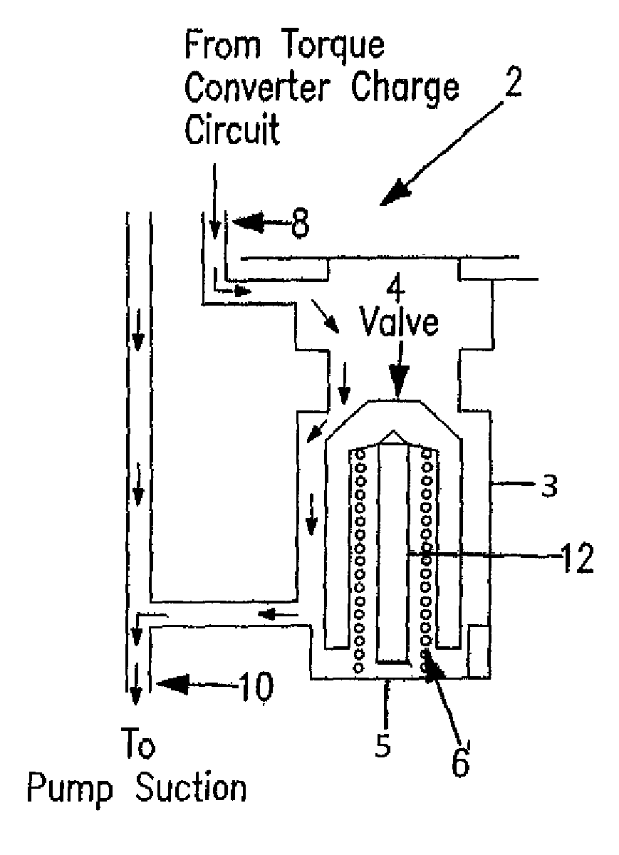
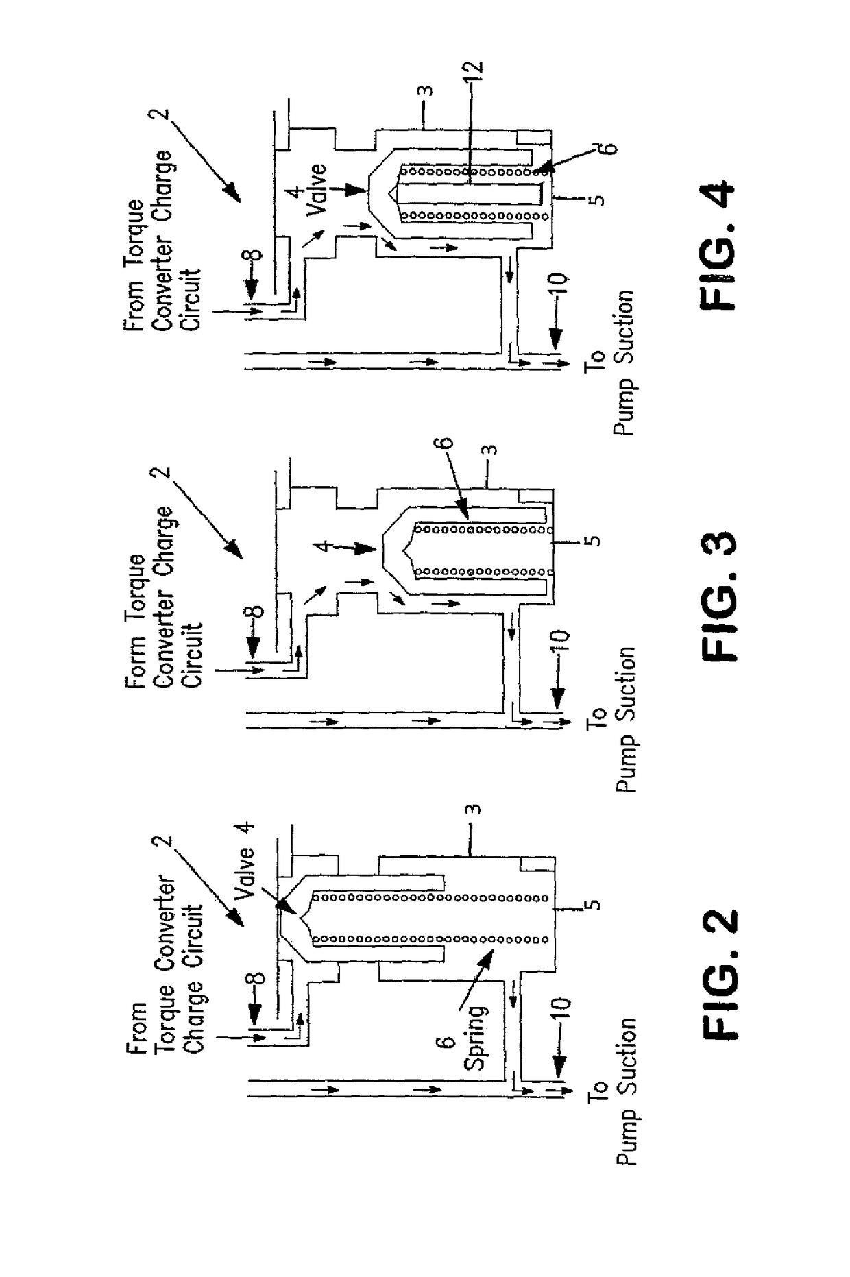
[0014]FIG. 2 of the drawing illustrates a portion of the hydraulic circuitry illustrated by FIG. 1, isolating the torque converter check valve, which is generally designated by reference numeral 2 in FIG. 2. In FIG. 2 of the drawing, the torque converter check valve is illustrated as being in its fully closed position. The torque converter check valve includes a valve element designated by reference numeral 4, a check valve spring designated by reference numeral 6, a fluid flow line designated by reference numeral 8, and a fluid flow line designated by reference numeral 10. The valve element is movable within a housing 3 having a clos...


PUM

PropertyMeasurementUnit
hydraulic pressureaaaaaaaaaa
resilient forceaaaaaaaaaa
distanceaaaaaaaaaa

Abstract

A torque converter check valve has a valve element movable between a closed position and an open position by applying hydraulic pressure to a portion of the valve element and by applying a resilient force by a resilient element acting on another portion of the valve element. A spacer element is provided to act on the valve element and limit movement of the valve element in the direction in which the resilient element is compressed to reduce wear on the resilient element during operation of the torque converter check valve.

Description

[0001]The present patent application claims the benefit of U.S. Provisional Patent Application Ser. No. 61 / 574,651, filed on Aug. 8, 2011, pursuant to 35 U.S.C. 119 (e).BACKGROUND OF THE INVENTION[0002]The methods and systems of the present invention are directed to the modification and improvement of transmissions for automotive vehicles, more commonly referred to as “factory installed” transmissions, installed in automotive vehicles by an original motor vehicle manufacturer. The invention is more particularly directed to improvements to “factory installed” transmissions for the four speed 98-04 Honda Odyssey, the five speed 98-04 Honda Odyssey, and the Acura 3.2 TL.[0003]The present inventor owns the following United States patents, the disclosures of which are expressly incorporated by reference into the present patent application: U.S. Pat. No. 4,449,426, issued May 26, 1984; U.S. Pat. No. 4,711,140, issued Dec. 8, 1987; U.S. Pat. No. 4,790,938, issued Dec. 13, 1988; U.S. Pat. N...

Claims


Application Information

Patent Timeline
Patent Type & Authority Patents(United States)
IPC IPC(8): F16H61/02F16H61/12
CPCF16H61/0276F16H61/12Y10T137/7837F16H2061/1264Y10T29/49716F16H2061/0279
Inventor YOUNGER, GILBERT W.
Owner TRANSGO LLC
Why Eureka
Try Eureka