Electrical fault restricting system

a technology of fault restriction and electrical system, applied in the direction of emergency protective arrangements for limiting excess voltage/current, emergency protective arrangements for automatic disconnection, instruments, etc., can solve the problems of difficult identification of actual electrical parameters, damage to electrical systems and/or equipment, and inability to provide accurate information, etc., to reduce damage costs, reduce damage costs, and save considerable restoration time

Inactive Publication Date: 2012-12-25
JOSHI MUKUNDLAL
View PDF7 Cites 3 Cited by
  • Summary
  • Abstract
  • Description
  • Claims
  • Application Information

AI Technical Summary

Benefits of technology

[0013]The further object of the invention is to reduce damages to electrical system and / or electrical equipment occurring due to electrical fault and so the surrounding electrical system and / or equipment(s) are also saved from effect of fault, which reduces damage cost and save considerable restoration time.
[0014]The further object of the invention is to identify fault location and its condition easily and quickly and have the invention suitable for use with electronic circuits including a microprocessor.
[0015]The further object of the invention is that every sensed / measured fault abnormality is noticed, analyzed, recorded as data history, accessed for performance of electrical system and / or electrical equipment, and the electrical system and / or electrical equipment is prevented from severe effects by tripping at preliminary stage of fault.

Problems solved by technology

So it is very difficult to identify actual electrical parameters particularly current due to fault.
It is clear when level of fault reaches at higher stage, it may damage severely to electrical system and / or equipment.
Moreover, the present systems are on bases of assumptions for some type of fault hence they do not provide accurate results.
But the fault cannot be noticed by alarming at preliminary stage and also the location at which the fault has occurred cannot be identified.
Moreover, when the fault reaches at severe stage, the faulty area can be badly affected which may result into total shut down of electrical system and / or electrical equipment.
The existing systems are not able to provide any records of abnormality for further analysis, which is essential for preventive maintenance, work in electrical system and / or electrical equipment.
In existing systems, abnormality in electrical system and / or electrical equipment is not identified at its preliminary stage of fault, that fault event may not be minimized near to zero level.
The existing systems do not give any indication of the sensed signal in developing stage of fault and there by they are unable to prevent the further development of fault in electrical system and / or electrical equipment and may also damage to the electrical system and / or electrical equipment.
The existing systems are not able to identify the location of fault.
Hence it takes more time to restore the affected electrical system and / or equipment.

Method used


Image

  • Electrical fault restricting system
  • Electrical fault restricting system
  • Electrical fault restricting system

Examples


Embodiment Construction

[0017]The proposed invention is now described in detail with the help of drawings as under:

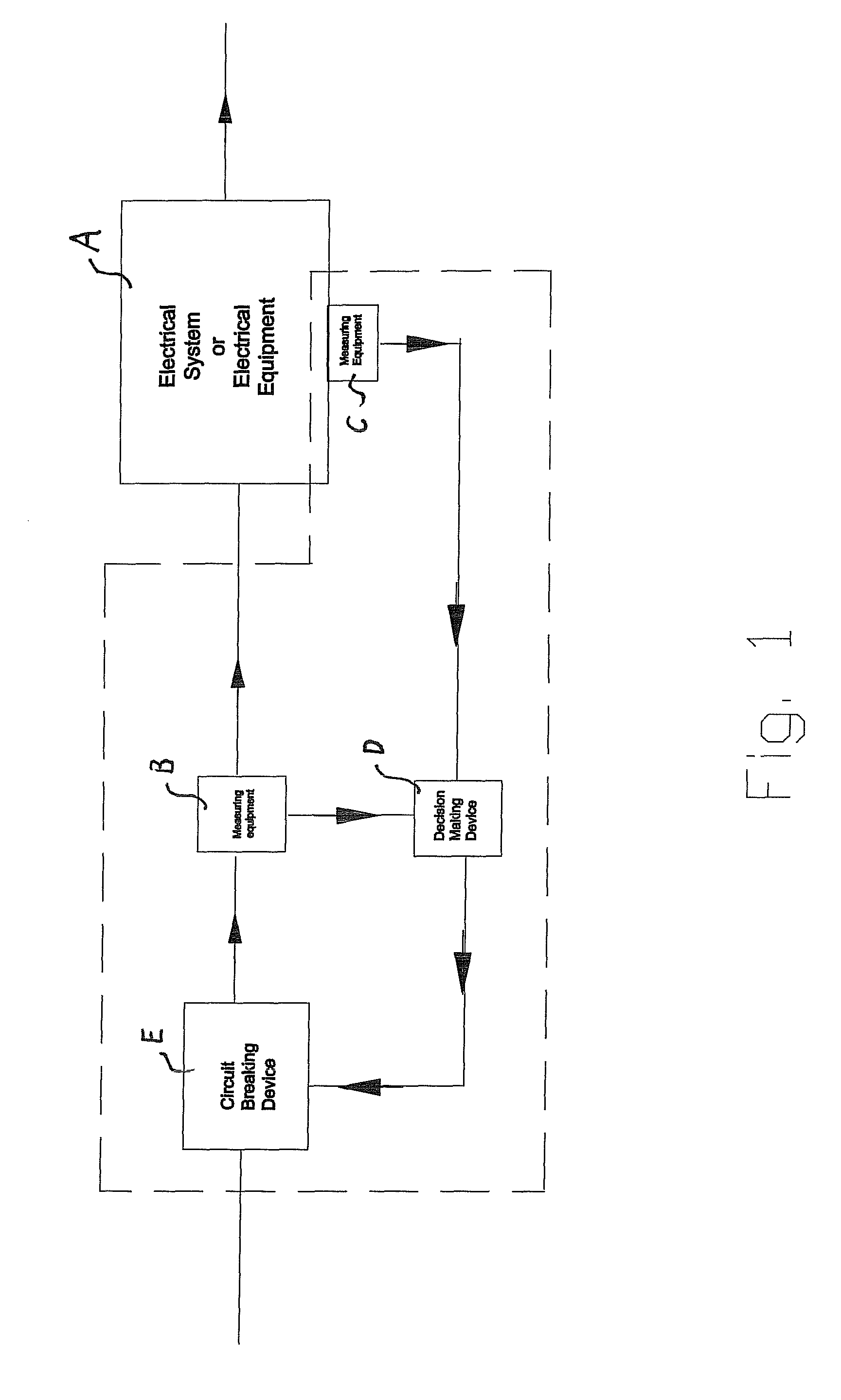
[0018]FIG. 1 shows diagrammatical arrangement of existing electrical fault restricting system.

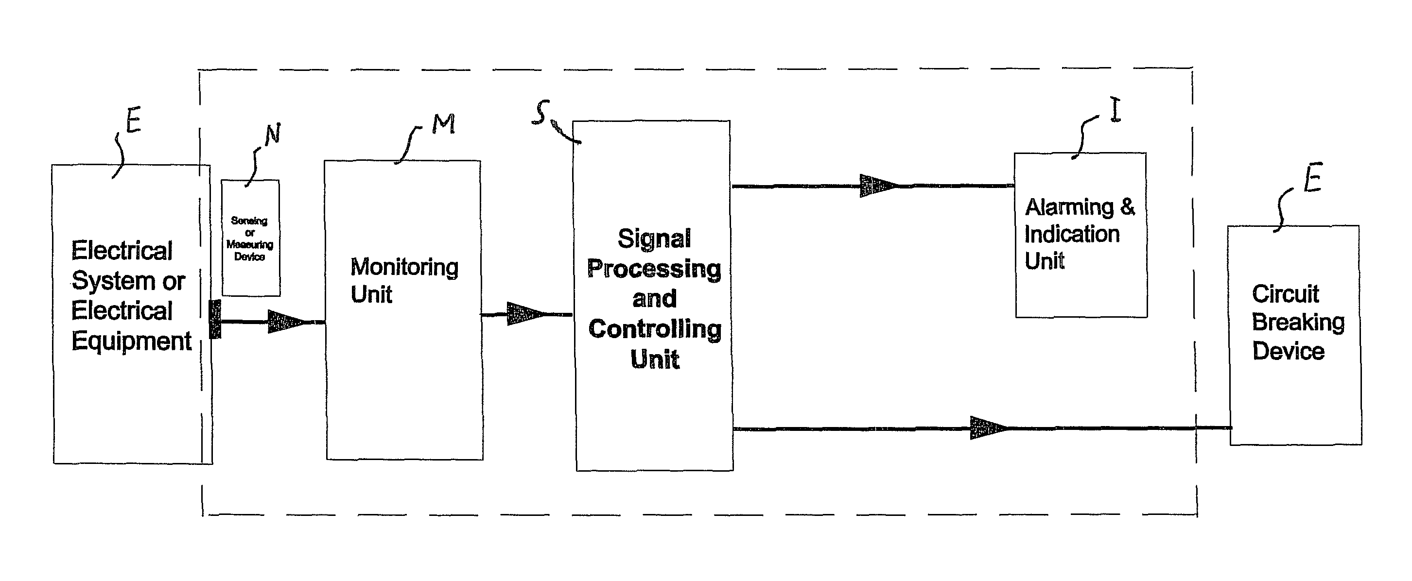
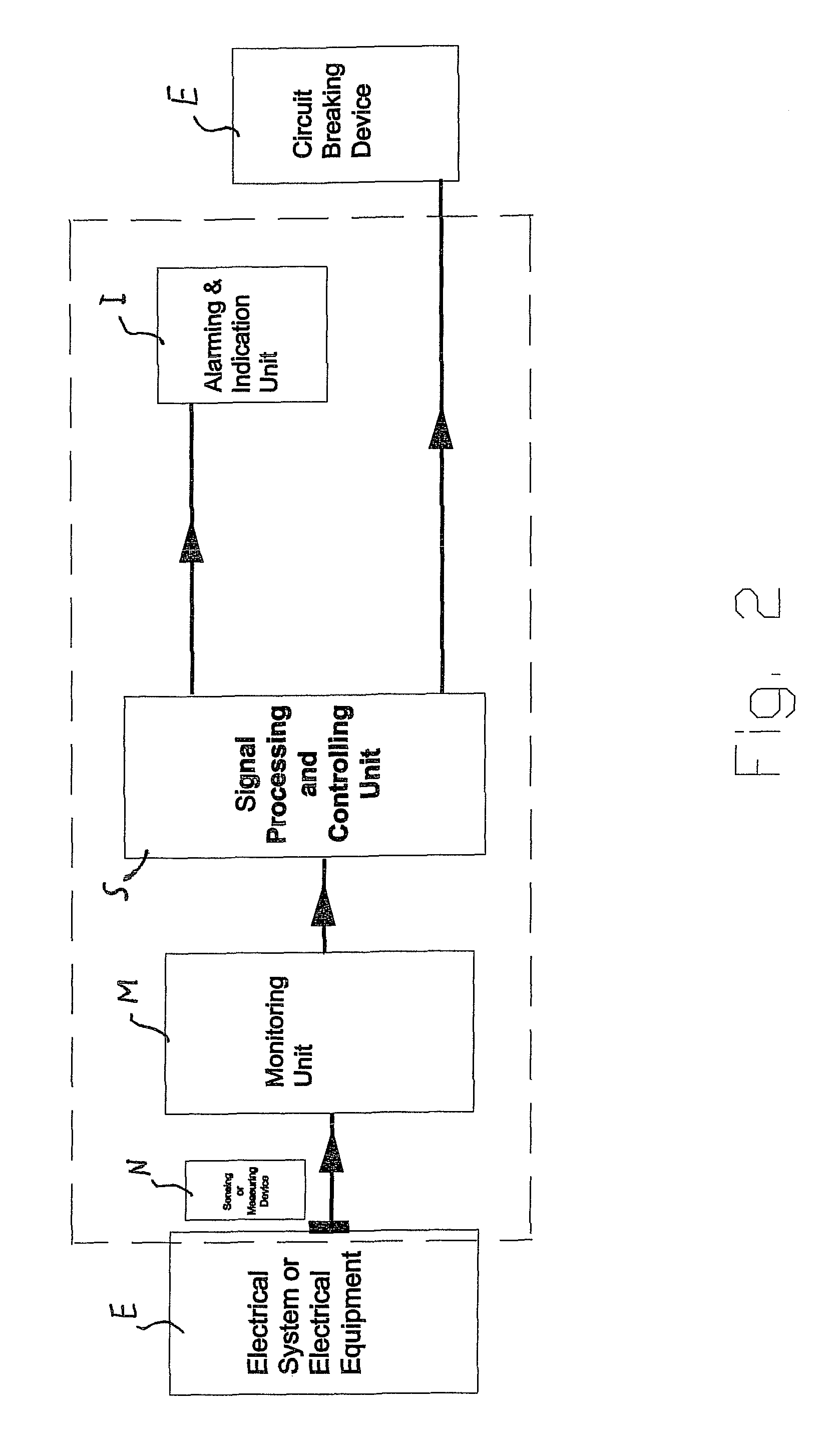
[0019]FIG. 2 shows block diagram of electrical fault restricting system with required facility of alarming and tripping command, indicating and display of required data.

[0020]FIG. 3 shows block diagram of electrical fault restricting system with required facility of alarming and tripping command, indicating and display of required data, data history storage and display of condition at a location of fault at time of fault.

[0021]FIG. 4 shows block diagram of electrical fault restricting system working in coordination with central data processing and decision making unit with required facility of alarming and tripping command, indicating, data display, data history storage and display of condition at fault location at time of fault.

DETAILED DESCRIPTION OF SPECIFIC EMBODIMENTS

[0022]FIG. 1 shows diagrammat...


PUM


Abstract

Electrical fault restricting system for an electrical equipment and/or electrical system has a monitoring unit placed at location of interest to sense or measure electrical fault occurred with the help of sensing or measuring device which is further connected to signal processing and controlling unit which receives data collected by the monitoring unit that provides output for fault identification, alarming and controlling actions to alarming. An indication unit and command for trip signal to circuit breaking device where processed data of data collecting and processing unit are stored at data history storage. A display unit for back reference monitoring unit provides images to image receiver. A processor and controlling unit further provides processed images to an additional data history storage and display unit for future analysis of conditions where plurality of signal processing and controlling unit is inter connected with additional remote central controlling and data handling unit.

Description

BACKGROUND OF THE INVENTION[0001]The present invention is related to the electrical fault restriction system to be used in electrical system and / or electrical equipment. The present invention is particularly related to the electrical fault restriction system by which electrical fault can be restricted from preliminary stage.[0002]It is necessary that any electrical system and / or electrical equipment must be protected from severe effects of electrical faults. There are various types of faults affecting the system like short circuit fault, over current fault, open circuit fault, thermal hot spot and earth fault. In any electrical equipment / system hot spot develops due to loose connections or overloading and sparks, arcs develops due to insulation failure say earth fault or phase to phase fault / short circuits, and due to open circuits.PRIOR ART[0003]There are systems available for fault restriction that work for all type of voltage class where they identify electrical fault with the he...

Claims


Application Information

Patent Timeline
Patent Type & Authority Patents(United States)
IPC IPC(8): H02H3/00
CPCH02H3/04
Inventor JOSHI, MUKUNDLAL
Owner JOSHI MUKUNDLAL
Why Eureka
Try Eureka