

Ion entry/exit device
a technology of entry/exit device and ion, which is applied in the direction of electron/ion optical arrangement, particle separator tube details, instruments, etc., can solve the problems of more problematic timing between rapid changing ion signals and subsequent analysers
- Summary
- Abstract
- Description
- Claims
- Application Information
AI Technical Summary
Benefits of technology
Problems solved by technology
Method used
Image

Examples
Embodiment Construction
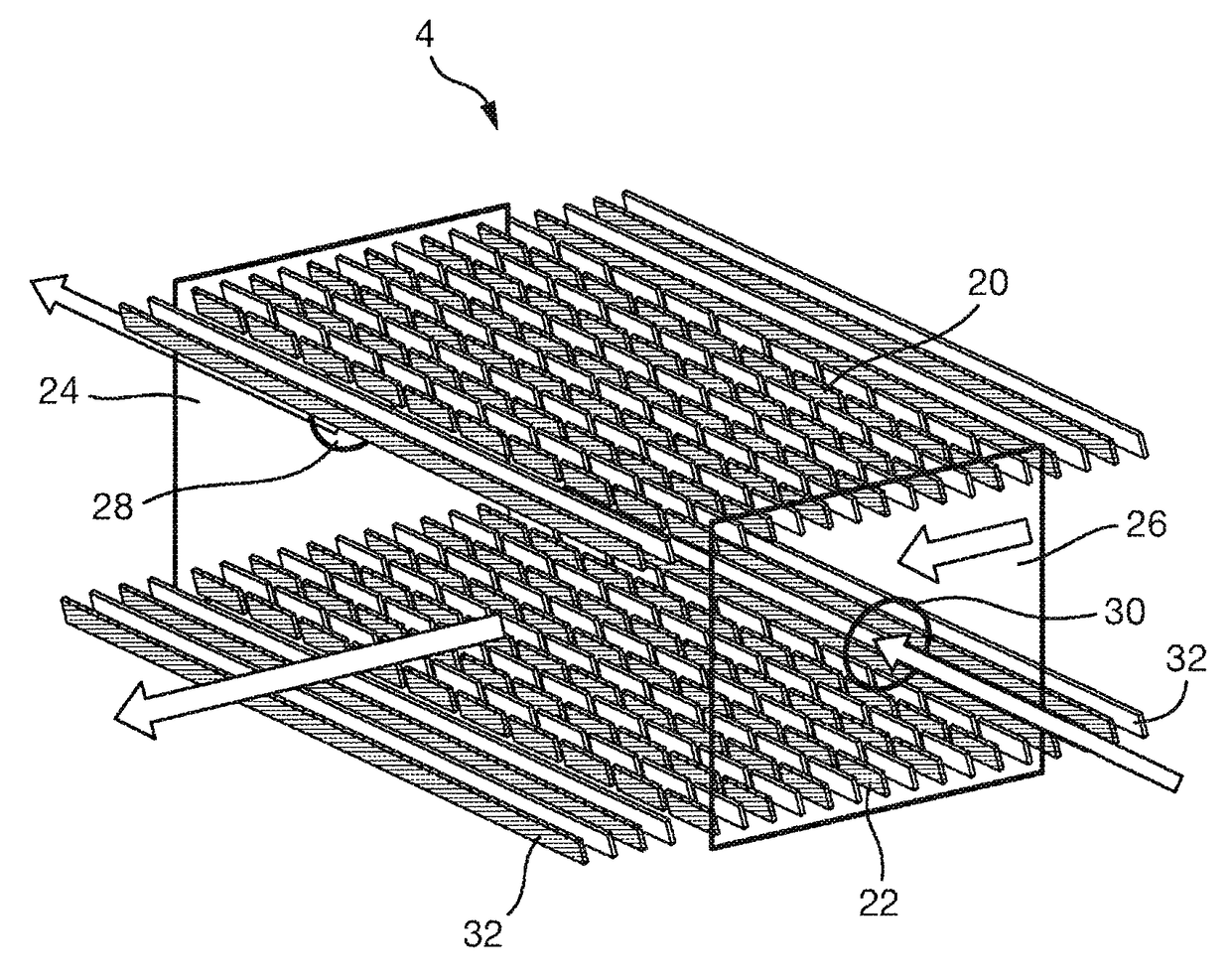
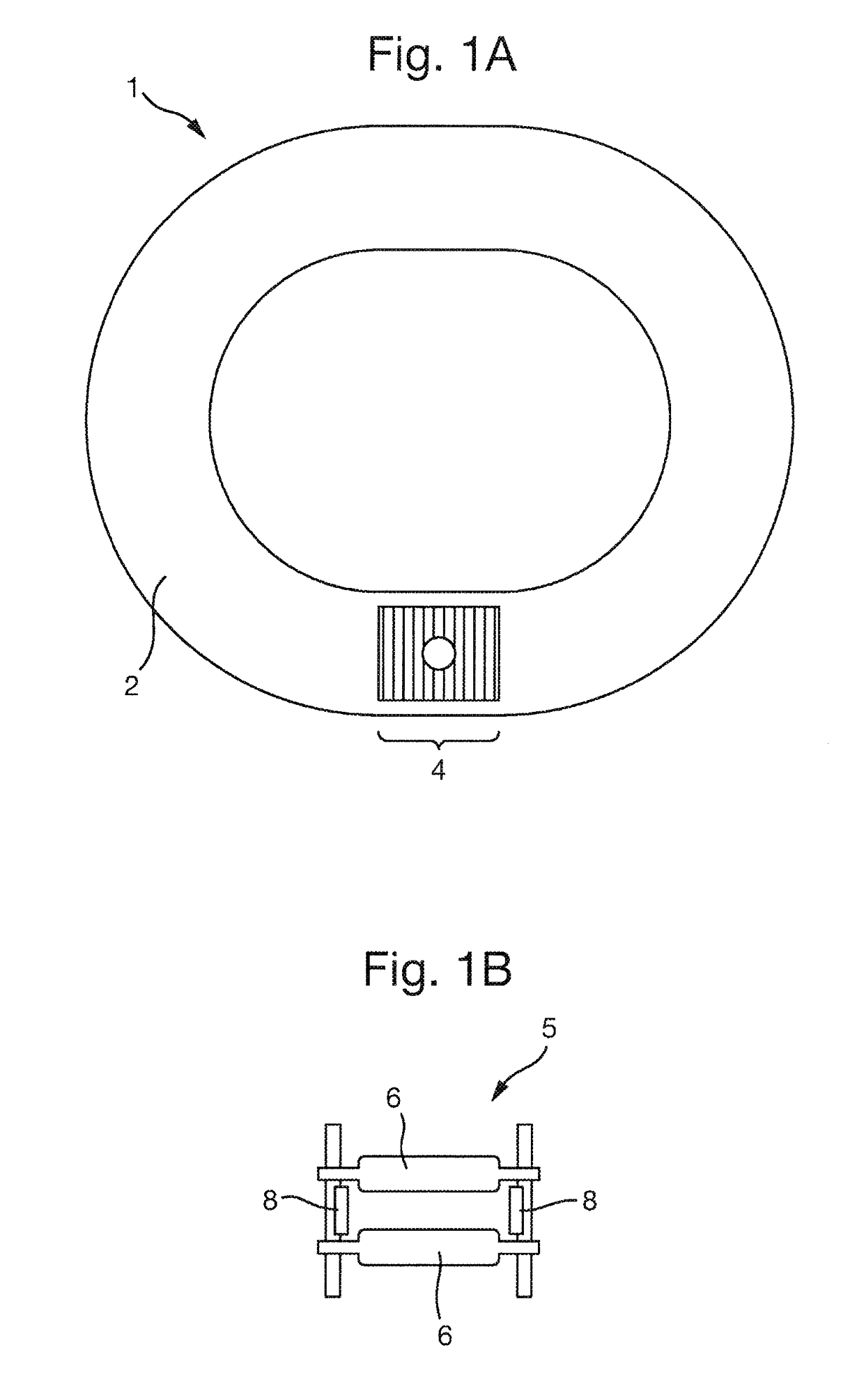
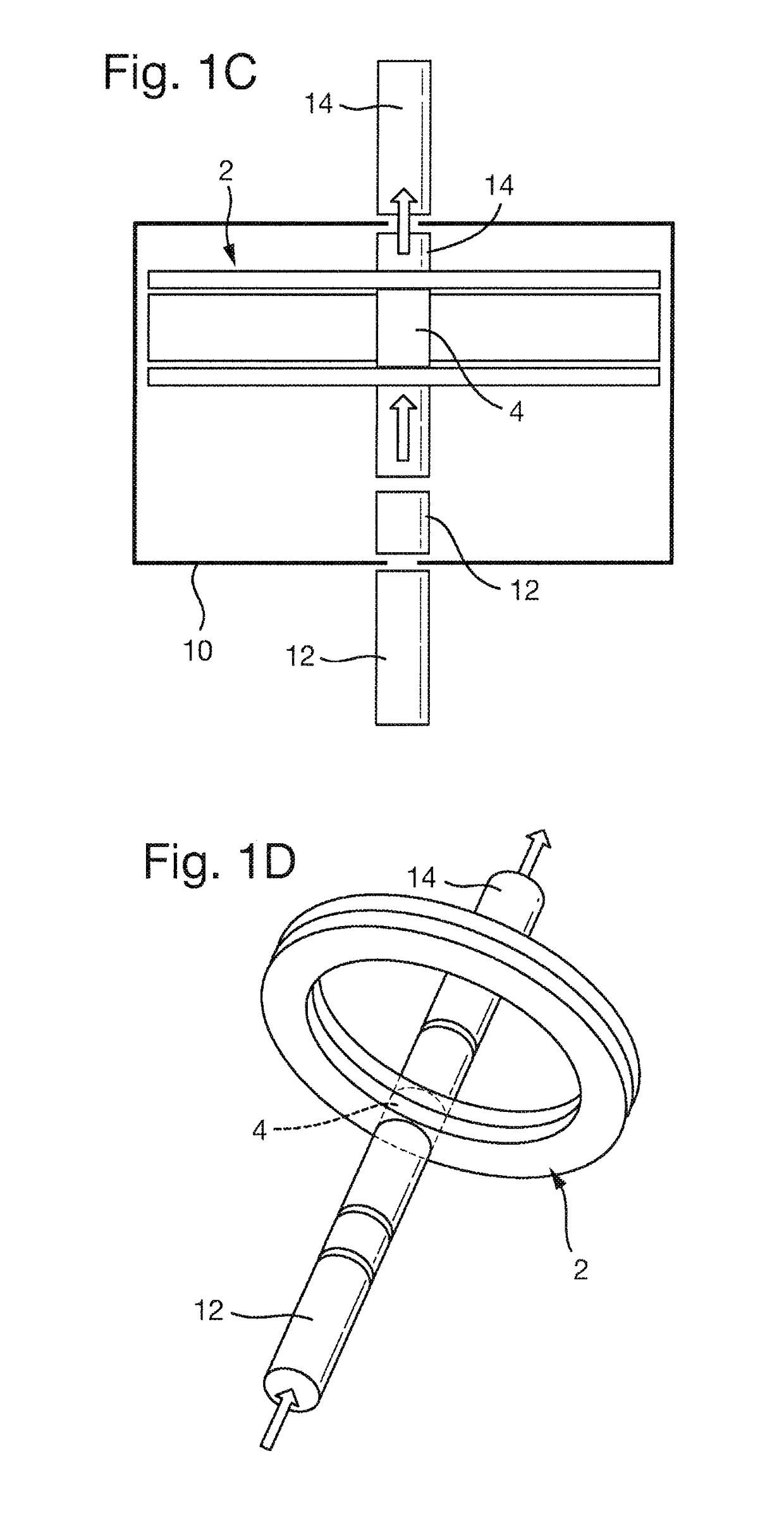
[0103]FIG. 1A shows a front view of a schematic of an ion mobility separator (IMS) according to a preferred embodiment of the present invention. The IMS device 1 comprises a closed-loop drift cell 2 around which the ions are guided in use. The drift cell 2 comprises a plurality of electrodes that act to confine the ions to an axial path that extends around the closed-loop drift cell 2. The drift cell 2 also comprises electrodes that urge the ions along the axial length of the drift cell. The ion guide is filled with a background gas such that as the ions are urged around the drift cell 2 they collide with the gas molecules and separate according to their ion mobilities through the gas. The ions may be urged around the closed-loop drift cell 2 once or multiple times before being extracted through an exit region 4. The ions may be urged around the drift cell 2 by applying one or more electrical potential that travels axially along the drift cell 2, or less preferably by a static DC po...
PUM
| Property | Measurement | Unit |
|---|---|---|
| voltage | aaaaa | aaaaa |
| frequency | aaaaa | aaaaa |
| pressure | aaaaa | aaaaa |
Abstract
Description
Claims
Application Information