Device and method for cutting off an end section of a can blank

a technology of end sections and can blanks, applied in the field of devices and methods for cutting off end sections of can blanks, can solve problems such as uneven edges or jagged edges, and achieve the effect of sufficient tim

Inactive Publication Date: 2018-06-05
SCHULER PRESSEN GMBH & CO KG
View PDF38 Cites 0 Cited by
  • Summary
  • Abstract
  • Description
  • Claims
  • Application Information

AI Technical Summary

Benefits of technology

[0007]In accordance with the present invention, the device for cutting a can blank comprises a first conveyor arrangement comprising several can receptacles, said conveyor arrangement rotating about a first axis of rotation. Each can receptacle is disposed to accommodate one can blank. The can blank is positioned and held in the can receptacle by means of a holding arrangement. The holding arrangement comprises a plate that can be rotated about a second axis of rotation, in which case the second axis of rotation coincides, in particular, with the longitudinal axis of the can blank. A cutting means moves so as to be adapted to the movement of the conveyor arrangement and, in particular, to the rotational speed of the can receptacle about the first axis of rotation. During the cutting operation, the affected can blank can thus be moved about the first axis of rotation, as well as about the second axis of rotation. Because any stopping or delay of the conveyor arrangement during the cutting operation is not required, machining of a large number of can blanks per unit of time is possible. In a first exemplary embodiment of the device, the conveyor arrangement rotates at 210 revolutions per minute and comprises ten can receptacles. In this manner, it is possible to process 2100 cans per minute. The duration of contact of the cutting means with the can blank is very short and preferably less than 100 milliseconds, for example 15 to 50 milliseconds.
[0009]Alternatively, it is also possible to use a laser beam as the cutting means. A laser source for generating the laser beam is stationarily mounted to a machine frame, so that the conveyor arrangement and the can blanks will move relative to the laser source. For example, a solid state laser and, preferably, a fiber laser can be used as the laser source. The laser beam may be emitted as a continuous beam during the duration of contact. The device comprises a deflecting arrangement that is arranged between the laser source and a machining region and deflects the laser beam to the can blank in the machining region. To accomplish this, for example, the deflecting arrangement may have at least one reflecting surface. In doing so, the deflection of the laser beam is adapted to the rotational movement of the conveyor arrangement or the can blank about the first axis of rotation. The location of the focus of the laser beam remains unchanged relative to the first and / or second axes of rotation while the can blank is being machined. Due to the deflection that is adapted to the movement of the can blank about the first axis of rotation and due to the rotation of the blank can about its longitudinal axis, the can blank can be machined along is entire circumference, without requiring a change of the location of the focus. At the same time, the conveyor arrangement rotates continuously about the first axis of rotation.
[0012]In a preferred embodiment, the holding arrangement comprises a holding element that can be moved between an inoperative position and a holding position. In the inoperative position, the holding element clears the can receptacle, so that a can blank can be accepted or released. In the holding position, the holding element secures and supports the can blank in the can receptacle. To accomplish this, a part of the holding element can support the can blank on its side surface, so that an exact positioning of the can blank is ensured for laser cutting.
[0013]In order to support the can blank, the holding element may comprise, for example, an arcuate or annular support element. In the holding position, this support part may partially or fully enclose the side surface of the can blank in peripheral direction. In conjunction with this, it is particularly advantageous if the support part has an air bearing on its inside. As a result of this, the can blank can be precisely positioned. In addition, damage by scratching or even deformations are prevented.
[0015]The plate may be continuously driven or, alternatively, stop, when the can blank is received into the can receptacle and / or is released from the can receptacle. When, as is the case in one embodiment, the plate is non-rotatably connected with a drive wheel, the rotation of the can blank about its longitudinal axis can be achieved very simply by rotation of the drive wheel. In order to achieve a rotation of the drive wheel, for example, an arcuate drive rail can be provided coaxially with respect to the first axis of rotation. When the drive wheel comes into contact with the inside of the arc of the drive rail, said wheel rolls off on this side and causes a rotation of the plate about the second axis of rotation. Preferably, the length of the arc-internal side of the drive rail is greater than the circumference of the drive wheel, so that the plate or the can blank performs more than one complete rotation about the second axis of rotation while the drive wheel abuts against the contact rail. This ensures that there is sufficient time available for completely cutting off an axial end section of the can blank. Furthermore, it is possible, in a simple manner, to stop the plate while it receives and / or releases a can blank.

Problems solved by technology

Depending on the process by means of which this can blank is being manufactured, the edge may be uneven or jagged.

Method used


Image

  • Device and method for cutting off an end section of a can blank
  • Device and method for cutting off an end section of a can blank
  • Device and method for cutting off an end section of a can blank

Examples


Embodiment Construction

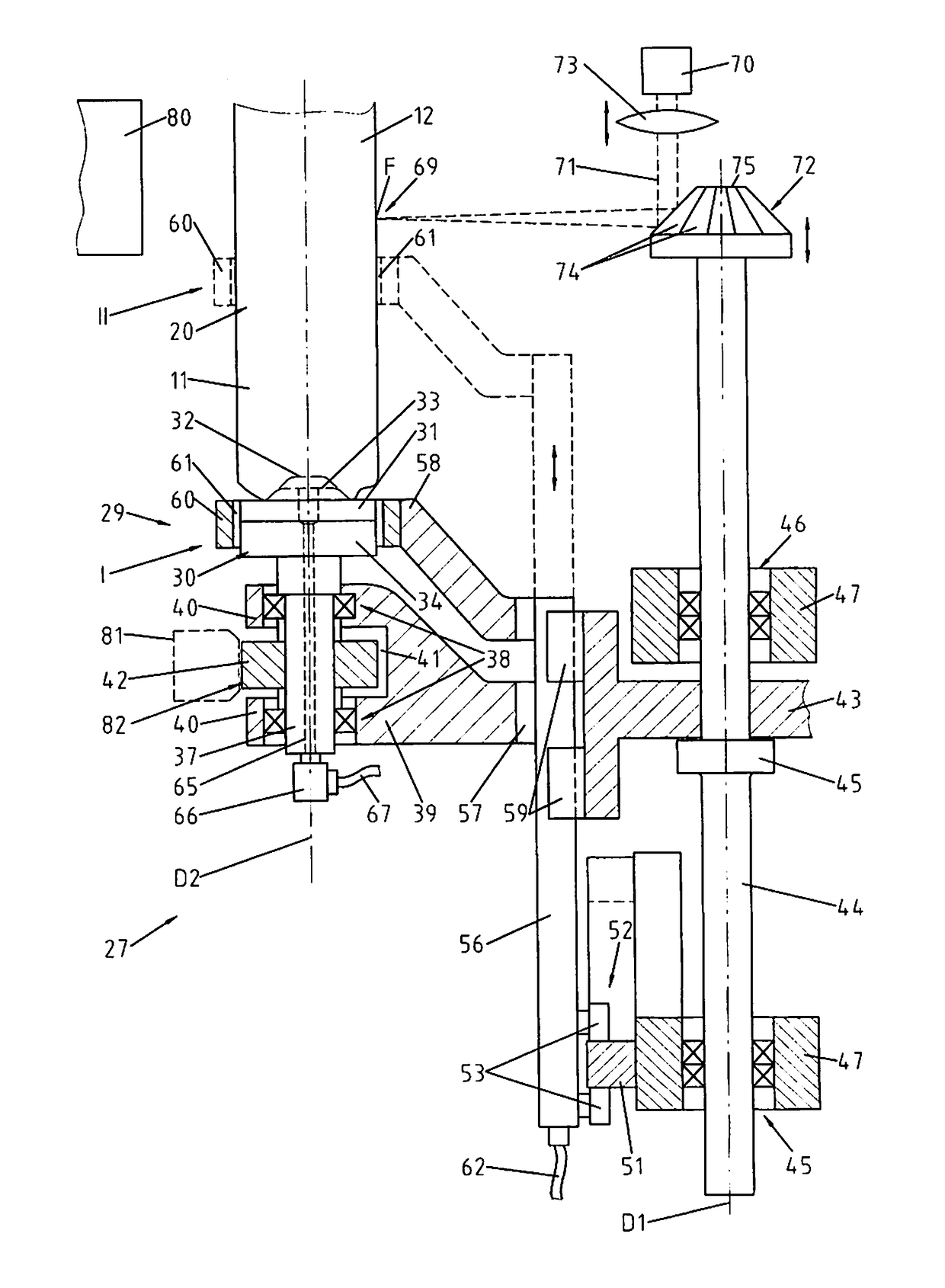
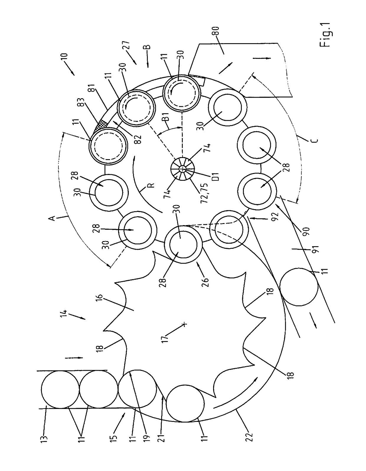
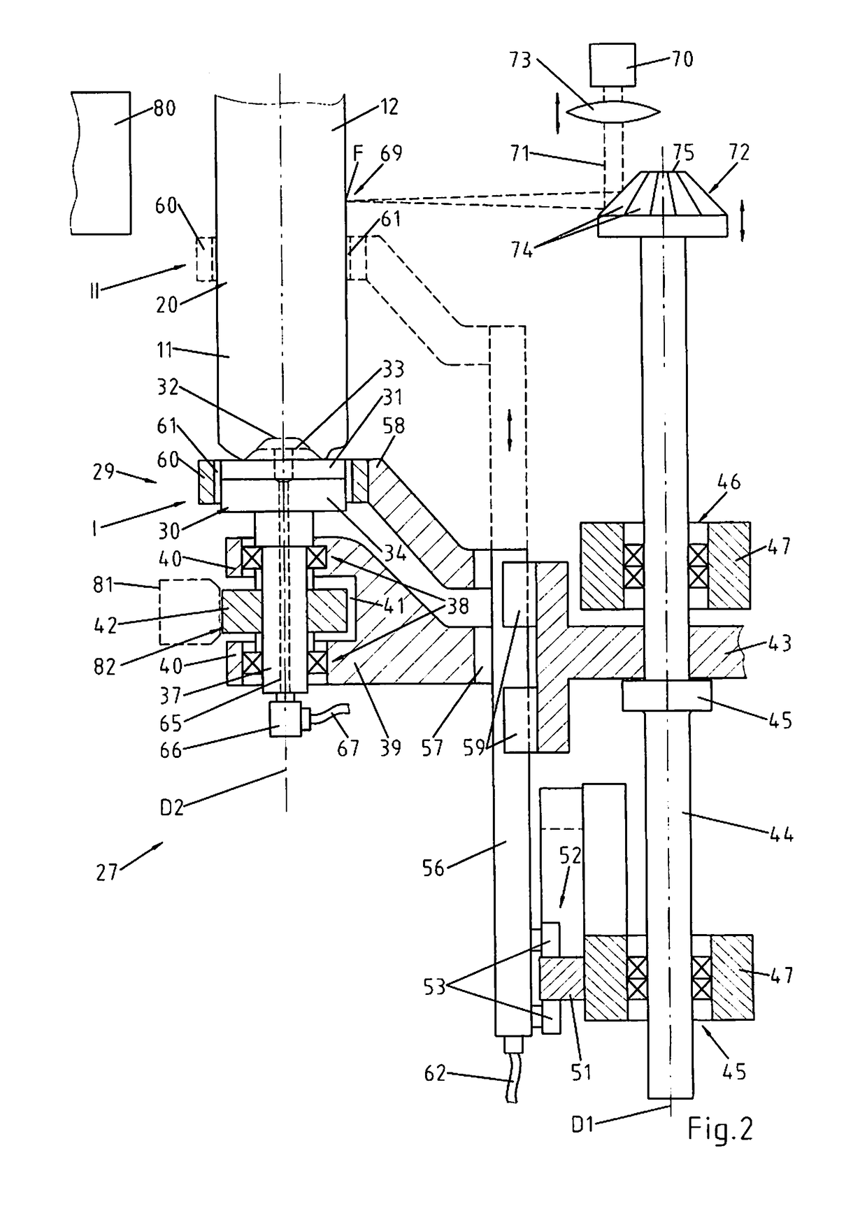
[0021]FIGS. 1 and 2 show a device 10 for cutting can blanks 11 by means of a laser and, in particular, for cutting off an axial end section 12 of the can blank 11.

[0022]Via a supply channel 13, can blanks 11 are fed to a separating arrangement 14 that sequentially accepts the can blanks 11 at a receiving location 15 and continues to transport them at a distance from each other. To accomplish this, the separating arrangement 14 comprises a transport wheel 16 that is supported so as to be rotatable about a transport wheel axis of rotation 17. In the exemplary embodiment, the transport wheel 16 rotates in counter-clockwise direction. On its outside periphery, the transport wheel has several, for example ten, transport recesses 18 at regular distances, each of said transport recesses being disposed for transporting one can blank 11. The transport wheel recesses 18 have a first recess section 19 that, preferably, has the form of circular arc, the progress of said circular arc in the pref...


PUM

PropertyMeasurementUnit
axis of rotationaaaaaaaaaa
rotationaaaaaaaaaa
distanceaaaaaaaaaa

Abstract

The invention is to a device and method, for cutting a can blank in which case an end section of the can blank is severed. The can blank is moved by means of a conveyor arrangement at a constant speed about a first axis of rotation. Preferably, a laser beam is used as the cutting means. A deflecting arrangement deflects the laser beam to a focal point where the side surface of the can blank is located. Due the rotation of the can blank about its longitudinal axis, the axial end section of said can blank is severed. The focal point of the laser beam does not change relative to the longitudinal axis of the can blank during the laser cutting operation.

Description

CROSS REFERENCE TO RELATED APPLICATION[0001]The present patent application is based upon and claims the benefit of German patent application no. 10 2011 001 521.3, filed on Mar. 24, 2011; and PCT application no.: PCT / EP2012 / 055187, filed Mar. 23, 2012.BACKGROUND OF THE INVENTION[0002]The invention relates to a method, as well as to a device, for laser cutting a can blank. In particular, the device and the method are to be used for cutting off the axial end section of a can blank. The can blank has a side surface and a can bottom. Depending on the process by means of which this can blank is being manufactured, the edge may be uneven or jagged. In these cases it is necessary that the axial end section of the can blank be severed with the use of a cutting means. The cutting means may be a laser beam or a mechanical cutting tool.[0003]A method for the manufacture of a metal can has been known from publication DE 28 01 475. It suggests the removal of the axial end section by laser cuttin...

Claims


Application Information

Patent Timeline
Patent Type & Authority Patents(United States)
IPC IPC(8): B26D7/06B21D51/26B23D31/00B65G47/84B26D3/16B23K26/38B26D7/01
CPCB26D7/0625B21D51/26B23D31/001B26D3/166B26D7/01B65G47/846B23K26/38Y10T83/4734
Inventor BLEI, KLAUSGUNTHER, UWE
Owner SCHULER PRESSEN GMBH & CO KG
Why Eureka
Try Eureka