Concrete forming system

a technology of concrete and forming panels, applied in endless track vehicles, manufacturing tools, transportation and packaging, etc., can solve the problems of requiring a significant amount of time and labor for each wall to be built, affecting the construction wall significantly, and the failure to properly align the panels

Active Publication Date: 2018-06-05
TGR CONSTR INC
View PDF51 Cites 12 Cited by
  • Summary
  • Abstract
  • Description
  • Claims
  • Application Information

AI Technical Summary

Problems solved by technology

The forms may be constructed on-site which requires a significant amount of time and labor for each wall built.
On larger projects, this can require a significant amount of panels which each must be manually moved and reset in different positions, which is extremely labor and time intensive.
Failure to properly align the panels can significantly impact the constructed wall—sometimes even requiring that such a defective wall be torn down and the process started again.
F...

Method used


Image

  • Concrete forming system
  • Concrete forming system
  • Concrete forming system

Examples


Embodiment Construction

A. Overview

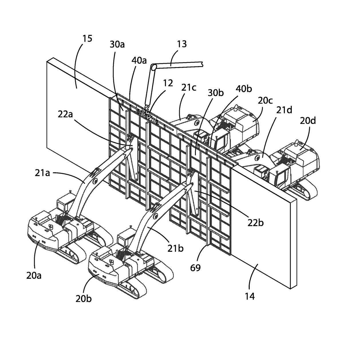
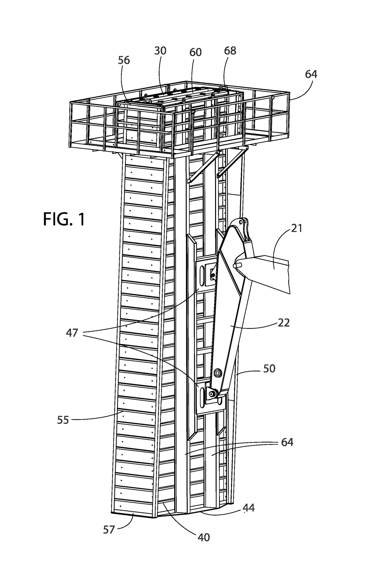
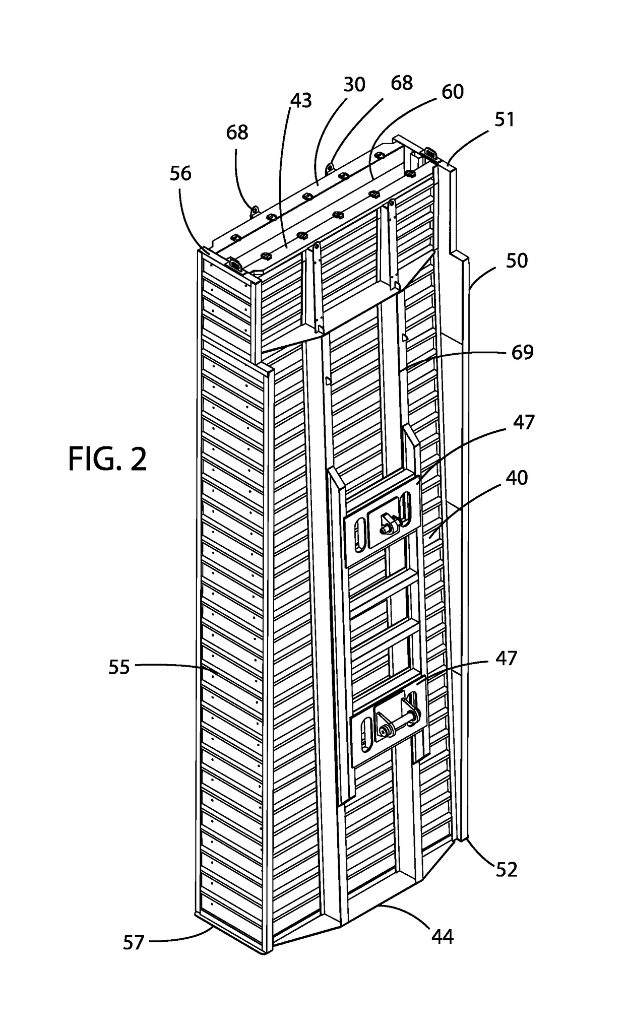
[0056]An example concrete forming system 10 generally comprises a first wall 30 having a first end 31, a second end 32, an upper end 33, and a lower end 34. As shown in FIGS. 1-6, the system 10 may also include a second wall 40 having a first end 41, a second end 42, an upper end 43, and a lower end 44; a first sidewall 50 connected between the first ends 31, 41 of the first wall 30 and the second wall 40; and a second sidewall 55 connected between the second ends 32, 42 of the first wall 30 and the second wall 40. A cavity 62 is defined between the first wall 30, the second wall 40, the first sidewall 50, and the second sidewall 55. The cavity 62 is adapted to receive a volume of concrete 12 and retain the concrete 12 during the curing process. An opening 60 formed within the upper ends 31, 41 of the first wall 30, second wall 40, first sidewall 50, and second sidewall 55 is fluidly connected with the cavity 62; with the opening 60 being adapted to receive the concrete 1...


PUM


Abstract

A concrete forming system for reducing the time and labor required for the framing, pouring, and curing of concrete walls. The concrete forming system generally includes concrete forms including a first wall, a second wall opposing the first wall, and a pair of sidewalls. A cavity is formed between the walls; with an opening being fluidly connected to the cavity. A first vehicle is connected to the first wall and a second vehicle is connected to the second wall. Using the vehicles, the positioning and orientation of the walls may be adjusted. After the walls have been placed and oriented, the vehicles will hold the walls in place as concrete is poured into the cavity through the opening. The concrete is allowed to cure into a structure; after which the vehicles and walls may be moved to another location to repeat the process.

Description

CROSS REFERENCE TO RELATED APPLICATIONS[0001]Not applicable to this application.STATEMENT REGARDING FEDERALLY SPONSORED RESEARCH OR DEVELOPMENT[0002]Not applicable to this application.BACKGROUNDField[0003]Example embodiments in general relate to a concrete forming system for reducing the time and labor required for the framing, pouring, and curing of concrete walls.Related Art[0004]Any discussion of the related art throughout the specification should in no way be considered as an admission that such related art is widely known or forms part of common general knowledge in the field.[0005]Walls have been in use since biblical times. Walls in the past have been constructed of blocks, wood, metals, or concrete. When constructing concrete walls, a liquid concrete is generally injected into a form and allowed to cure into a solid concrete wall. The forms may be constructed on-site which requires a significant amount of time and labor for each wall built.[0006]Previous concrete forming sys...

Claims


Application Information

Patent Timeline
IPC IPC(8): E04G19/00E04G11/20B62D63/04B62D55/00E04G11/08
CPCE04G11/20E04G19/003B62D63/04B62D55/00E04G11/08B28B15/002
Inventor FISHER, THOMAS G.SCHAFER, GREGORY L.
Owner TGR CONSTR INC
Why Eureka
Try Eureka