Hybrid capacitive-inductive voltage converter

a capacitive-inductive voltage converter and hybrid technology, applied in the field of voltage converters, can solve the problems of discontinuous input current and output current, undesirable in many applications, and high induced noise in the system, and achieve the effect of rapid transient response and high control bandwidth

Active Publication Date: 2018-06-05
TEXAS INSTR INC
View PDF5 Cites 5 Cited by
  • Summary
  • Abstract
  • Description
  • Claims
  • Application Information

AI Technical Summary

Benefits of technology

[0013]Disclosed embodiments provide such a voltage converter topology with high control bandwidth, and thus rapid transient response.
[0016]Disclosed embodiments provide such a voltage converter topology that may be implemented with transistors of relatively low voltage rating, and thus with reduced chip area.

Problems solved by technology

However, because most modern electronic devices rely on only a single, positive polarity, external DC power supply voltage, circuitry must be provided within these systems to generate a negative DC voltage from the positive external power supply voltage.
While the inverting buck-boost topology presents an output voltage VOUT of a magnitude that can be either greater or smaller than that of input voltage VIN, it presents certain drawbacks and limitations that are undesirable in many applications.
One such drawback is that both the input current and the output current are discontinuous, conducting in one clock phase but not in the other, which is reflected in relatively high output voltage ripple and relatively high induced noise in the system.
However, this topology requires two inductors (or, alternatively, a coupled inductor), which adds cost to the system.
As a result, conventional inverting voltage converter topologies do not completely satisfy the need, in some modern system applications, for the generation of a negative output voltage with low ripple and fast transient response.
Conventional voltage converters therefore typically include a dedicated post-regulator, such as a negative low-drop-out (LDO) regulator, which reduces the conversion efficiency and also adds to the cost of implementing the voltage conversion function.

Method used


Image

  • Hybrid capacitive-inductive voltage converter
  • Hybrid capacitive-inductive voltage converter
  • Hybrid capacitive-inductive voltage converter

Examples


Embodiment Construction

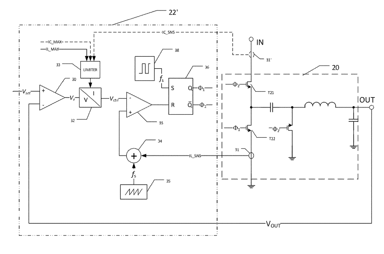
[0028]The one or more embodiments described in this specification are implemented into a voltage converter of the inverting buck type suitable for implementation in an integrated circuit, as it is contemplated that such implementation is particularly advantageous in that context. However, it is also contemplated that concepts of this invention may be beneficially applied to other applications, for example as implemented as a discrete circuit. Accordingly, it is to be understood that the following description is provided by way of example only, and is not intended to limit the true scope of this invention as claimed.

[0029]Attributes of switched-mode DC voltage converters that are desirable in many system implementations include low ripple in the output DC voltage, and rapid transient response of the converter to changes in the desired output voltage. Examples of applications that require these attributes of negative polarity DC voltages include high-performance analog circuits such a...


PUM


Abstract

An inverting buck voltage converter constructed of a switched-mode hybrid topology, with a capacitive input stage and an inductive output stage. The input stage operates as a charge pump to charge a flying capacitor connected in series with an inductor in the output stage. Clock circuitry generates first and second non-overlapping clock phases. In the second clock phase, the flying capacitor is charged to the input voltage, with a flying node between the flying capacitor and the output inductor connected at ground through a rectifier, while in the first clock phase, the flying capacitor supports the inductor current. The arrangement of the flying capacitor and inductor is such that the voltage appearing at the output terminal is inverted from the input voltage. Continuous output current is provided. Current limiting techniques protect the flying capacitor from overcurrent conditions.

Description

CROSS-REFERENCE TO RELATED APPLICATIONS[0001]Not applicable.STATEMENT REGARDING FEDERALLY SPONSORED RESEARCH OR DEVELOPMENT[0002]Not applicable.BACKGROUND OF THE INVENTION[0003]This invention is in the field of voltage converters. Embodiments are more specifically directed to switched mode DC-DC voltage converter circuits.[0004]Many electronic circuits and systems require the application of a negative DC voltage to one or more circuit nodes. For example, a negative bias may be required by certain component types, as a necessary power supply voltage to particular output devices such as displays, or to increase the performance and dynamic range of analog circuits. However, because most modern electronic devices rely on only a single, positive polarity, external DC power supply voltage, circuitry must be provided within these systems to generate a negative DC voltage from the positive external power supply voltage. Several architectures, or topologies, for DC-DC voltage converters that...

Claims


Application Information

Patent Timeline
Patent Type & Authority Patents(United States)
IPC IPC(8): H02M3/158
CPCH02M3/158
Inventor LUEDERS, MICHAELBAYER, ERICHSCHAEFFNER, THOMASCALABRESE, GIACOMO
Owner TEXAS INSTR INC
Why Eureka
Try Eureka