Micro electromechanical device for tilting a body in two degrees of freedom

A technology of micro-electromechanical devices and degrees of freedom, which can be used in micro-structure devices, micro-structure devices, circuits, etc. composed of deformable elements, and can solve problems such as low bandwidth

Inactive Publication Date: 2008-01-16
KONINKLIJKE PHILIPS ELECTRONICS NV
View PDF0 Cites 7 Cited by
  • Summary
  • Abstract
  • Description
  • Claims
  • Application Information

AI Technical Summary

Problems solved by technology

[0006] Existing 2DOF deflection mirror devices use two independent suspension systems that limit deflection (too high angular stiffness) and control bandwidth (too much mass)
The c

Method used


Image

  • Micro electromechanical device for tilting a body in two degrees of freedom
  • Micro electromechanical device for tilting a body in two degrees of freedom
  • Micro electromechanical device for tilting a body in two degrees of freedom

Examples


Embodiment Construction

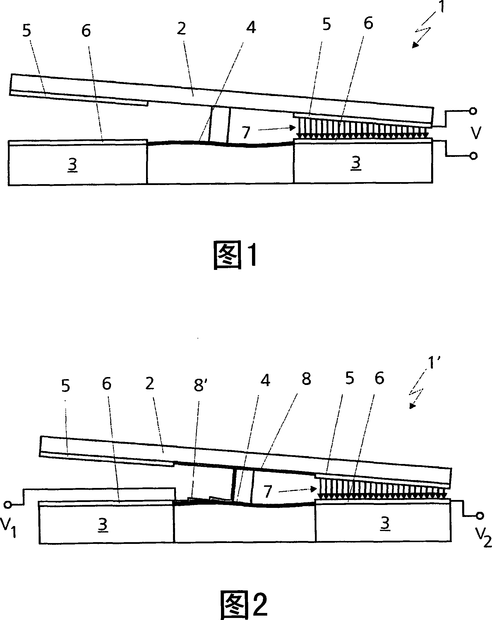
[0025] The present invention will be described below in conjunction with an optical element, specifically using a deflection mirror as a tilting object. In yet another embodiment, other tilted objects or optical elements may also be used.

[0026] As shown in FIG. 1 , a microelectromechanical device 1 for tilting an object, in particular a deflecting mirror 2 , with two degrees of freedom, comprises a carrier element 3 to which the deflecting mirror 2 is connected via a polymer membrane 4 . The deflection mirror 2 and the carrier element 3 comprise electrodes 5 and 6 respectively, wherein the deflection mirror 2 is tilted by the electrostatic force (electric field direction shown by arrow 7) between the electrode 5 of the deflection mirror 2 and the electrode 6 of the carrier element 3, A voltage is applied to the electrodes 5, 6 by a voltage source V. Polymer membrane suspension deflection mirror 2 made of materials such as polyimide or parylene can drive deflection mirror 2...


PUM


Abstract

The invention relates to a micro electromechanical device (1') for tilting a body (2) in two degrees of freedom comprising a carrier element (3) and a membrane (4), the body (2) being connected via the membrane (4) to the carrier element (3), wherein the body (2) and the carrier element (3) each comprise at least one electrode (5,6). The body (2) is tilted by means of electrostatic forces (7) between the at least one electrode (5) of the body (2) and the at least one electrode (6) of the carrier element (3) by an application of a voltage (V1,V2) to said electrodes (5,6) from a voltage source.

Description

technical field [0001] The present invention relates to a microelectromechanical device for tilting an object with two degrees of freedom, and to an optical scanning device including the microelectromechanical device for tilting an object. Background technique [0002] Optical devices such as scanners, optical couplers for optical networks, projection displays, etc. often require means to individually drive or tilt optical elements, specifically deflection mirrors, such as microelectromechanical systems (MEMS) for reflective deflection of light beams . [0003] There are basically two types of tilt-deflection mirror devices at present, namely the resonant type and the open-loop control type. [0004] Resonant deflecting mirror arrangements are used in scanning devices such as displays. The mirror acts as a mass point on a spring in its suspended state, resulting in a mechanical natural frequency. Since these mirrors are elastically suspended, their damping coefficients ar...

Claims


Application Information

Patent Timeline
IPC IPC(8): B81B3/00G02B26/08
CPCB81B3/0062G02B26/0841
Inventor M·T·梅韦斯D·范利洛普R·J·阿斯杰斯G·L·M·扬森E·C·E·范格鲁斯温D·M·布劳沃
Owner KONINKLIJKE PHILIPS ELECTRONICS NV
Why Eureka
Try Eureka