Transmission control device for automatic transmission

a transmission control and automatic transmission technology, applied in the direction of gearing control, gearing element, belt/chain/gearing, etc., can solve the problems of insufficient control of the downshift according to the corner characteristics, time-consuming, and particularly time-consuming to achieve the downshift from the high speed stag

Active Publication Date: 2018-06-12
HONDA MOTOR CO LTD
View PDF15 Cites 1 Cited by
  • Summary
  • Abstract
  • Description
  • Claims
  • Application Information

AI Technical Summary

Benefits of technology

[0016]With the present invention, the downshift control is performed based on either one of the first required speed change stage corresponding to the predicted rolling amount during the passage through the corner, and the second required speed change stage based on the minimum required inter-vehicle distance during the travelling through the corner. Accordingly, when travelling through the corner, it is possible to automatically perform the downshift control taking into consideration the characteristics of the corner and the inter-vehicle distance during the passage through the corner. This produces the excellent effect of automatically achieving the driver's intention of applying appropriate engine braking in front of the corner. The driver is therefore capable of traveling through the corner at ease.

Problems solved by technology

This can be time consuming.
Hence, it particularly takes time to achieve the downshift from the high speed stage to an intended speed change stage.
However, merely by performing the corner detection and downshift control according thereto as in the case with these conventional technologies, in some case, the downshift control according to characteristics of the corner is insufficient, or the result of the downshift control does not coincide with the driver's intention.

Method used


Image

  • Transmission control device for automatic transmission
  • Transmission control device for automatic transmission
  • Transmission control device for automatic transmission

Examples


Embodiment Construction

[0028]An embodiment of the present invention is described in detail below with reference to the accompanying drawings.

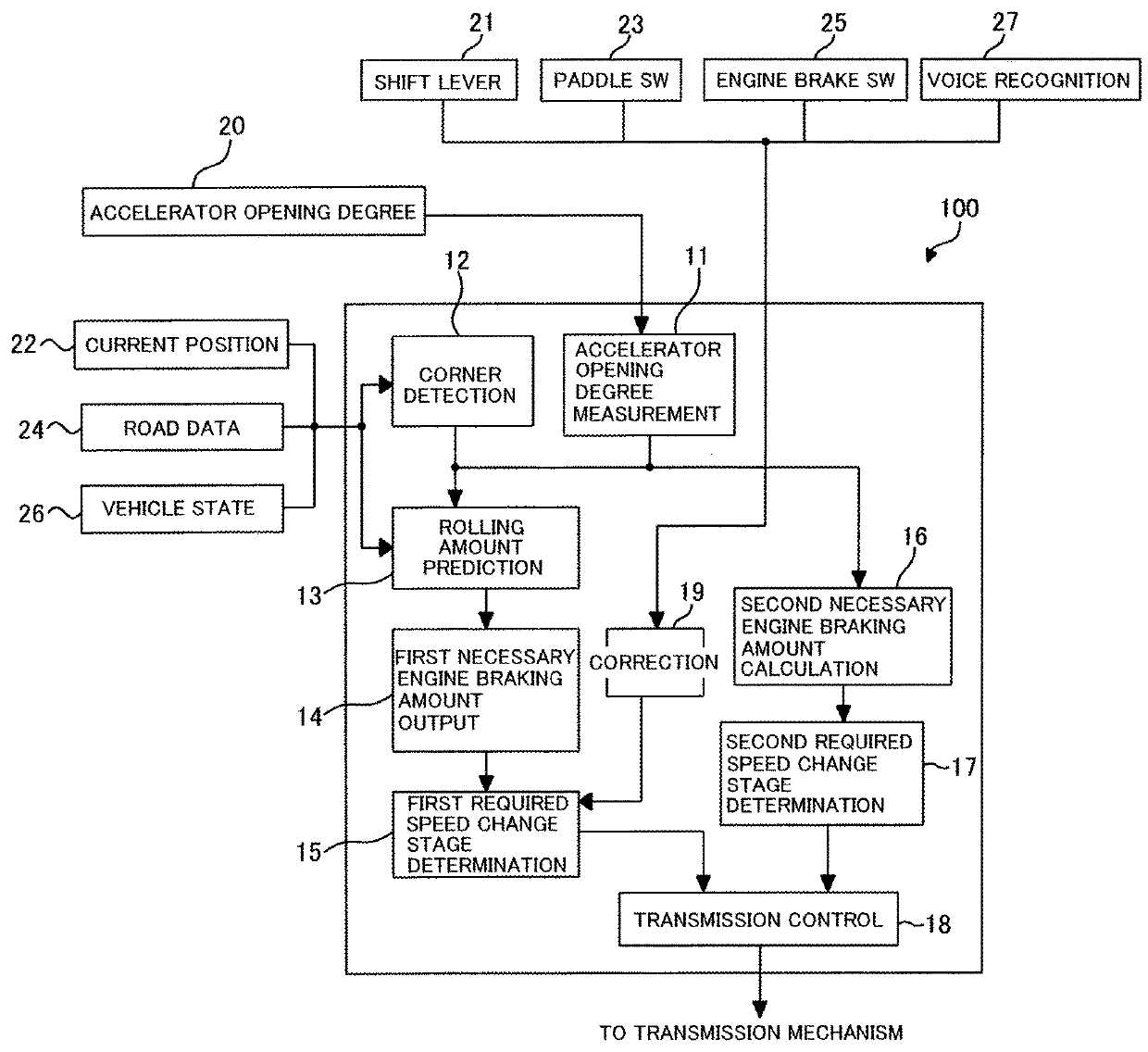
[0029]FIG. 1 is a functional block diagram that shows a configuration of a transmission control device for an automatic transmission according to an embodiment of the present invention. The automatic transmission 100 is intended to transmit output of an engine (not shown) to driving wheels (not shown), and includes a transmission mechanism made up of a torque converter (not shown) and a multistage transmission gear mechanism (not shown). The automatic transmission 100 also includes a transmission control device 10 for controlling a speed change operation of the transmission mechanism (hereinafter also referred to as “transmission control”), and is configured to select one of a plurality of speed change stages by the transmission control of the transmission control device 10.

[0030]The transmission control device 10 is made up of a CPU, memory, an A / D converter, a D / A ...


PUM


Abstract

A transmission controller includes: a corner detector that detects a corner; a predictor to predict a rolling amount based upon road data when the corner is detected and an accelerator opening degree is fully closed; a device to determine a first necessary engine braking amount in accordance with the rolling amount; a device to determine a first required speed change stage corresponding to the first necessary engine braking amount; a calculator to calculate a second necessary engine braking amount when the corner is detected and the accelerator opening degree is fully closed based upon a minimum required inter-vehicle distance with the vehicle ahead; a device to determine a second required speed change stage corresponding to the second engine braking amount; and a transmission controller to select, as a target speed change stage, either smaller one of the first or second required speed change stage, and then perform downshift control.

Description

TECHNICAL FIELD[0001]The present invention relates to a transmission control device for an automatic transmission and, more specifically, to downshift control in front of a corner.BACKGROUND ART[0002]In general, a driver of a vehicle may perform a downshift operation in front of a corner for the purpose of, for example, deceleration of the vehicle, stabilization of the vehicle behavior, or immediate generation of driving force at a rising of the corner. By performing the downshift operation in front of the corner, engine braking is effectively usable to achieve the deceleration of the vehicle, the stabilization of the vehicle behavior, or the like.[0003]When the downshift operation is performed by a manual operation in an automatic transmission, the driver performs the downshift by selecting a speed change stage one by one through, for example, a shift lever operation in a manual range, or an operation on a paddle switch disposed on a steering wheel. However, multi-staging of recent...

Claims


Application Information

Patent Timeline
Patent Type & Authority Patents(United States)
IPC IPC(8): F16H61/02F16H59/66F16H59/22F16H61/16F16H59/02
CPCF16H61/0213F16H59/22F16H59/66F16H61/16F16H2061/0237B60Y2300/18133F16H59/0204F16H2059/666F16H59/18F16H61/21
Inventor NOGUCHI, TOMOYUKI
Owner HONDA MOTOR CO LTD
Why Eureka
Try Eureka