Radially acting aftercooler for horizontal continuous casting

a technology of horizontal continuous casting and aftercooler, which is applied in the field of horizontal continuous casting, can solve the problems of graphite sleeves subject to rapid wear, reducing the cooling efficiency of aftercoolers, and graphite lined aftercoolers remain subject to a plurality of significant problems and limitations, so as to reduce the formation of oxides and witness marks on casting, increase cooling efficiency and wear resistance, and avoid oxide formation

Active Publication Date: 2020-08-27
AHRENS MAX +1
View PDF0 Cites 0 Cited by
  • Summary
  • Abstract
  • Description
  • Claims
  • Application Information

AI Technical Summary

Benefits of technology

[0008]Accordingly, it is a general object of the present invention to provide an improved aftercooler. It is a more particular object of the present invention to provide an improved aftercooler that avoids the need for lubricating graphite within the aftercooler passage and which increases cooling efficiency and wear resistance. It is a still more particular object of the present invention to provide an improved aftercooler that maintains a straight

Problems solved by technology

Unfortunately, the graphite sleeves are subject to rapid wear and reduce the cooling efficiency of the aftercooler.
The use of graphite lined aftercoolers remains subject to a plurality of significant problems and limitations.
The rapid wear of the graphite sleeves, caused by abrasion as the casting travels through the graphite lining, enlarges the sleeve passage.
The enlarged graphite sleeve passage results in a lack of contact between the casting and the graphite sleeve surface such that the casting is no longer tightly constrained as it travels through the aftercooler.
As a result, the casting becomes crooked.
In addition, the reduction of cooling efficiency caused by the graphite sleeves increases the metallurgical length of the casting allowing the formation of shrinkage pockets and voids within the casting.
Additional problems arise as the reduced cooling efficiency results in h

Method used


Image

  • Radially acting aftercooler for horizontal continuous casting
  • Radially acting aftercooler for horizontal continuous casting
  • Radially acting aftercooler for horizontal continuous casting

Examples


Embodiment Construction

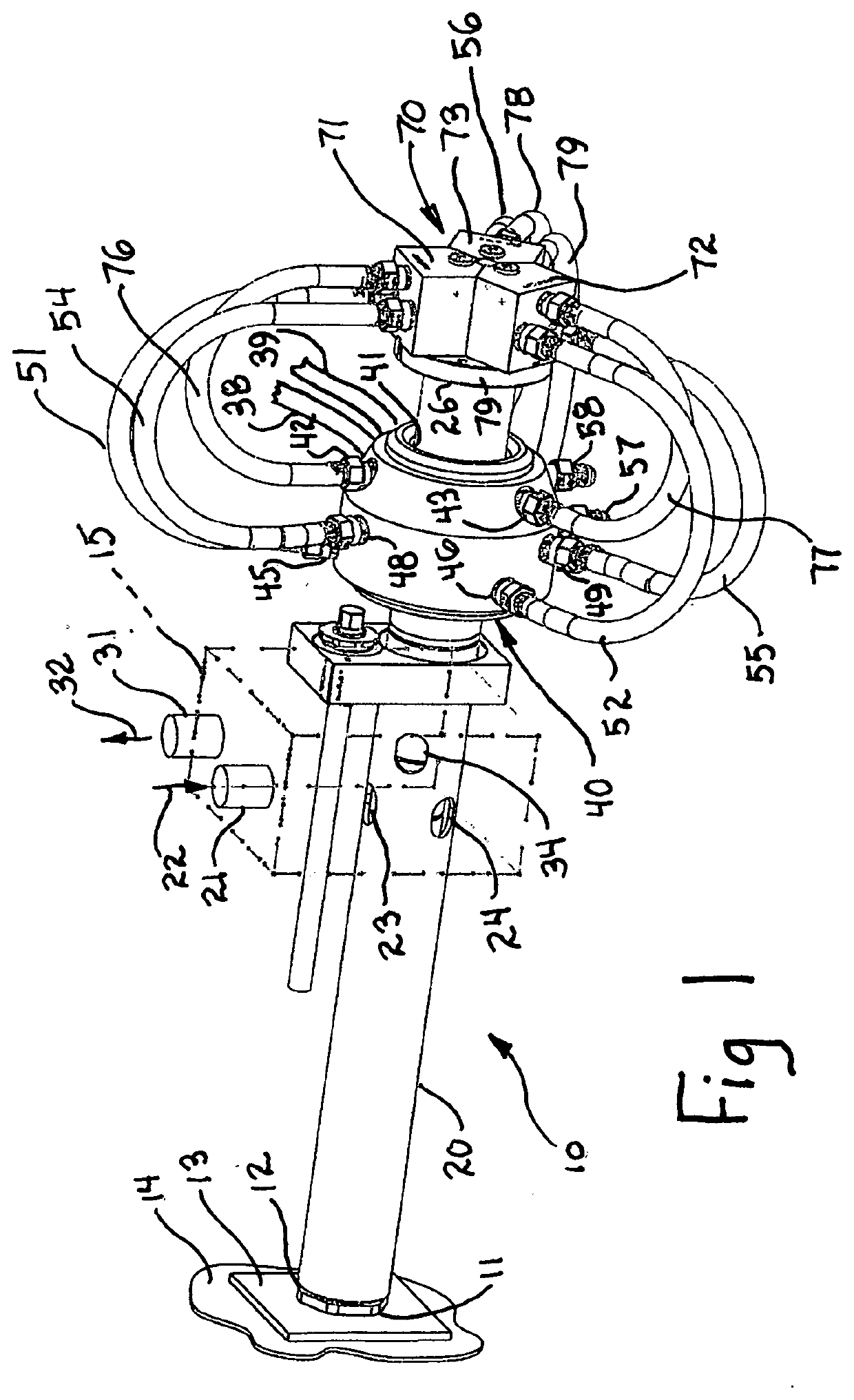
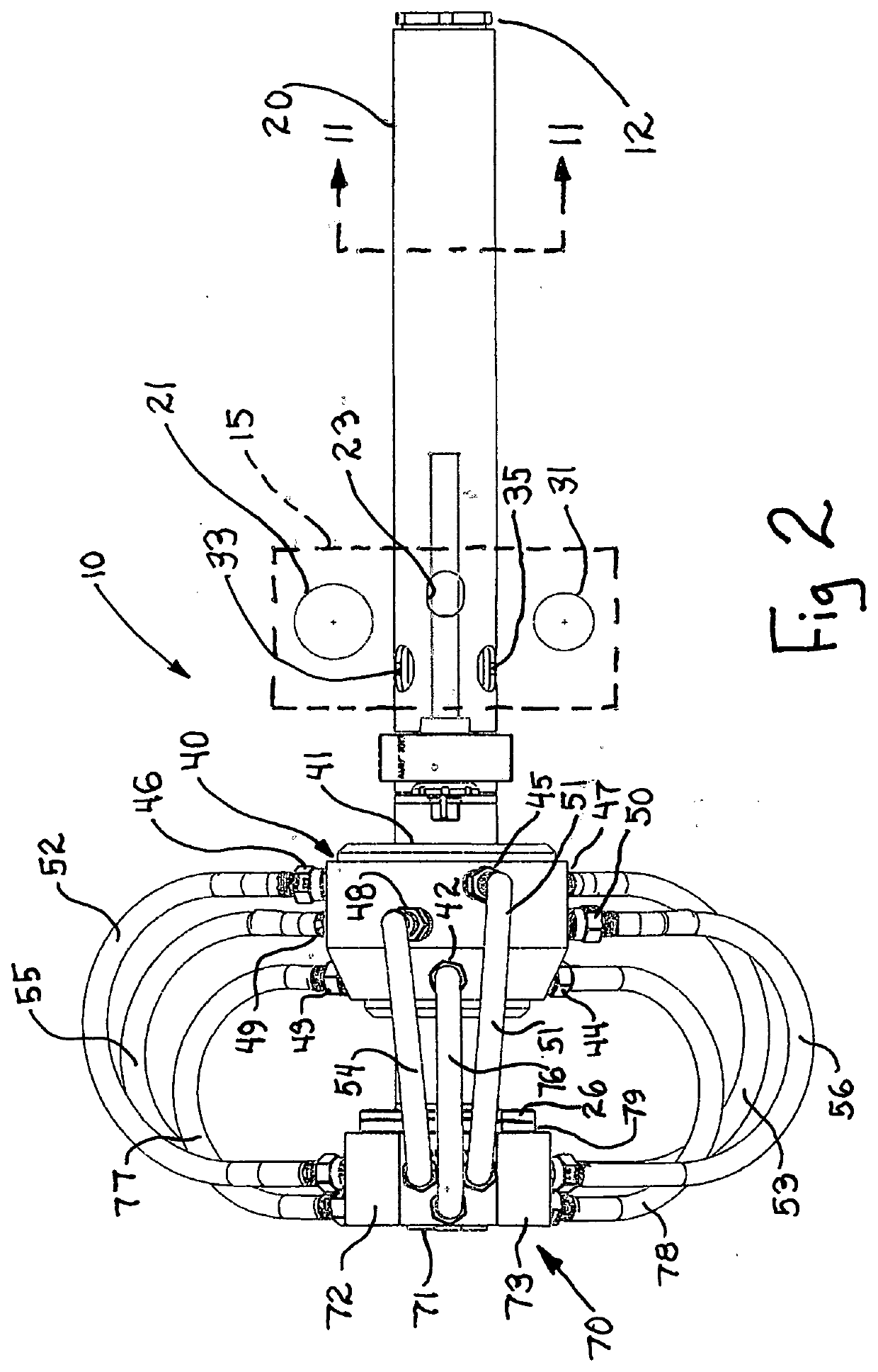
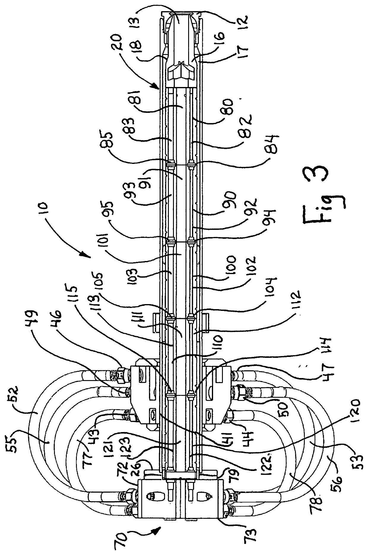
[0023]FIG. 1 sets forth a perspective view of a radially acting aftercooler constructed in accordance with the present invention and generally referenced by numeral 10. Aftercooler 10 includes an aftercooler barrel 20 supporting a die collar 12 at one end. Aftercooler barrel 20 further supports a mold holder 15 having a water input coupling 21 and a water output coupling 31. Aftercooler barrel 20 defines a plurality of water input apertures 23, 24 and 25 (aperture 25 not seen) together with a plurality of water output apertures 33, 34 and 35 (apertures 33 and 35 not seen).

[0024]Radially acting aftercooler 10 further includes an intermediate adapter 40 defining a center passage 41 therethrough. Center passage 41 receives a portion of aftercooler barrel 20 extending through center passage 41 and beyond. Intermediate adapter 40 supports a plurality of gas couplers 42, 43 and 44 (coupler 44 not seen). Intermediate adapter 40 further supports a plurality of aftercooler water input couple...


PUM

PropertyMeasurementUnit
Forceaaaaaaaaaa

Abstract

An aftercooler for horizontal continuous casting includes a plurality of aftercooler segments each of which includes a plurality of radially acting aftercooler sections. The radially acting sections each define inner surfaces which combine with, the remaining radially acting aftercooler sections to form an aftercooler passage. The, radially acting sections within each aftercooler segment are banded together by a plurality of resilient encircling bands. The bands draw the radially acting aftercooler sections together to constrain a casting within the casting passage. The plurality of aftercooler segments are provided with a surrounding coolant carrying jacket. A plurality of gas distribution passages are formed in the radially acting aftercooler sections which are provided with a flow of inert gas. The inert gas distributes itself between the surfaces of the casting and the surfaces of the aftercooler passage to prevent oxide formation and to ease the travel of the casting through the, aftercooler.

Description

FIELD OF THE INVENTION[0001]This invention relates generally to horizontal continuous casters and particularly to aftercoolers used therein.BACKGROUND OF THE INVENTION[0002]Horizontal continuous casters have become extremely pervasive in the metal casting arts enjoying particularly broad use in the casting of relatively thin elongated metal castings such as metal rod or wire. While the design and fabrication of horizontal continuous casters has been subject to substantial variation, generally all may be understood as a combination of the following basic elements. A supply of molten metal, often called a tundish, is positioned in communication with a discharge nozzle. The discharge nozzle is typically formed of a ceramic type material having the capability of withstanding the high temperatures of the molten metal and defining a metal flow passage therethrough. A cooled mold, often formed of copper, or copper alloy, metal is supported in communication, with the nozzle and includes a m...

Claims


Application Information

Patent Timeline
IPC IPC(8): B22D11/124
CPCB22D11/045B22D11/124B22D11/1246B22D11/143
Inventor AHRENS, MAXSPRIGGS, RODGER W.
Owner AHRENS MAX
Why Eureka
Try Eureka