Integrated motor/gear pump

a technology of integrated motors and gear pumps, applied in the direction of positive displacement liquid engines, piston pumps, liquid fuel engines, etc., can solve the problems of unbalanced axial, restricted space, and foregoing gear types, and achieve the effect of reducing nois

Inactive Publication Date: 2001-06-05
THE UNITED STATES OF AMERICA AS REPRESENTED BY THE SECRETARY OF THE NAVY
View PDF5 Cites 44 Cited by
  • Summary
  • Abstract
  • Description
  • Claims
  • Application Information

AI Technical Summary

Benefits of technology

In accordance with the present invention a reduced noise type of gear pump, formed by enmeshed pinion and ring gears rotatable about closely spaced offset axes within a pump chamber enclosed by a cylindrical bearing portion of a housing rotationally supporting the gears, is sealed between side plates within which stator windings are sealingly mounted as part of an integrated electric motor involving generation of magnetic fields produced internally in ...

Problems solved by technology

Various problems are however associated with the foregoing type of gear pump often related to th...

Method used


Image

  • Integrated motor/gear pump
  • Integrated motor/gear pump
  • Integrated motor/gear pump

Examples


Embodiment Construction

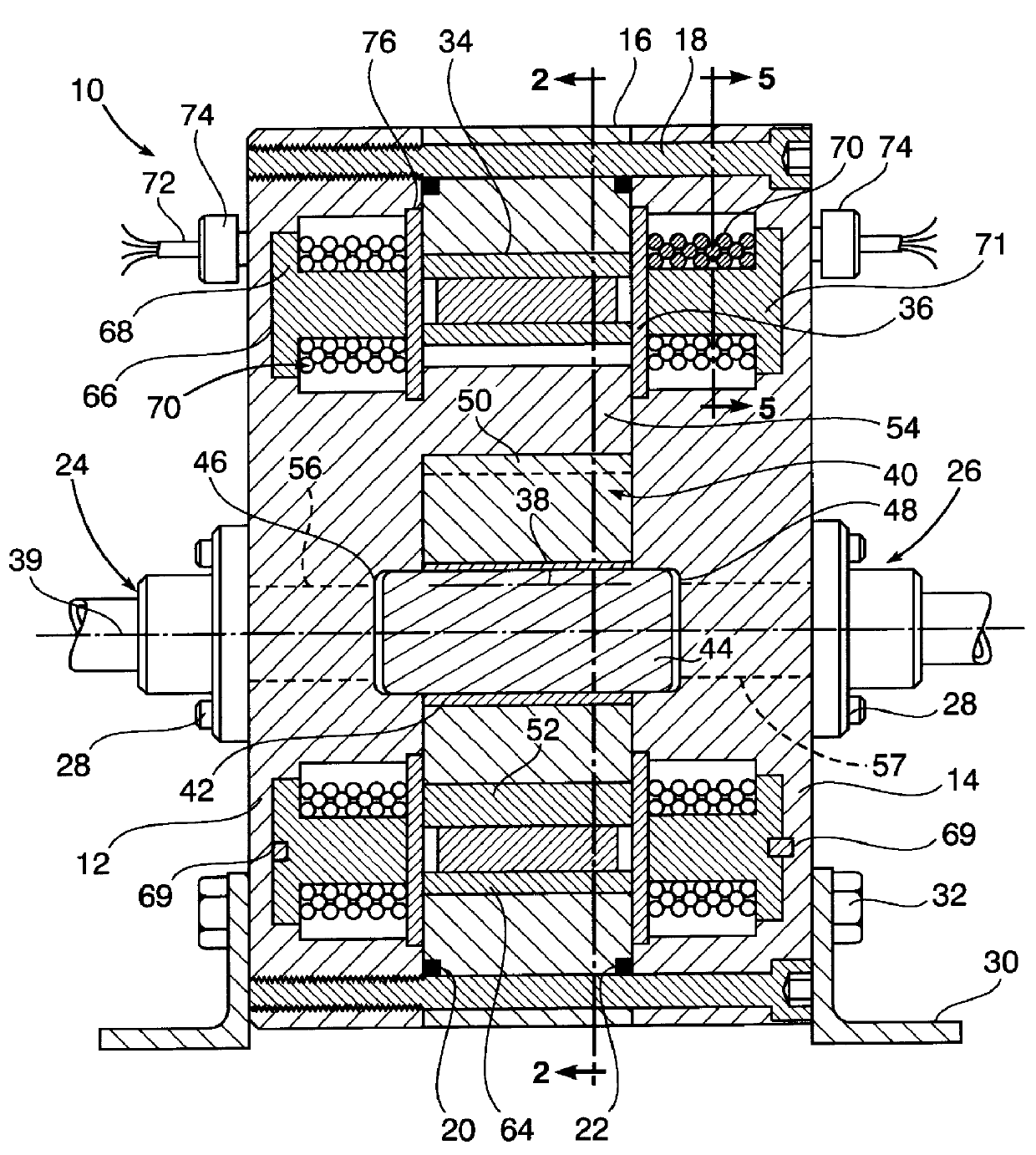
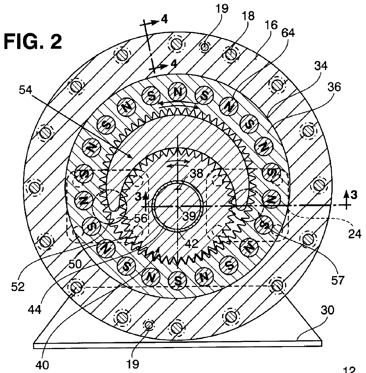
Referring now to the drawing in detail, FIG. 1 illustrates in side section an integrated motor / pump unit generally referred to by reference numeral 10 having a housing formed by a pair of flat circular side plates 12 and 14 axially separated by a circular bearing cylinder 16 to which the plates are secured after being radially aligned therewith. A plurality of circumferentially spaced fastener bolts 18 extend from the plate 14 through the cylinder 16 and are threadedly received within the plate 12 to interconnect the plates and cylinder, while precise radial alignment is achieved by two dowels 19 as shown in FIG. 2 extending parallel to the bolts 18 through the plates and cylinder. A pair of annular seals 20 and 22 are respectively carried by the cylinder 16 on opposite axially sides thereof for contact with the side plates 12 and 14 in close radially spaced relation to the bolts 18 so as to seal an internal pump chamber within the cylinder 16 between the plates 12 and 14. Inlet and...


PUM


Abstract

Pinion and ring gears intermeshed at one location within a pump chamber are rotationally supported therein by a cylindrical bearing portion of a housing sealingly enclosing said pump chamber between side plates of the housing within which stator windings are mounted in operative alignment with permanent magnets carried in one of the gears acting as a motor rotor as a result of interaction between such magnets and magnetic fields produced by electrical input power fed to the stator windings.

Description

The present invention relates in general to a gear pump driven by an electric drive motor internally formed therein.BACKGROUND OF THE INVENTIONGear pumps which feature polytoothed pinion and ring gears enmeshed at one location within a pump chamber so as to act as impellers for displacement of fluid in response to rotational torque applied to the pinion gear, are generally well known in the art as disclosed for example in U.S. Pat. No. 5,360,325 to Henry, IV et al. Such gear pumps are characterized by operation with substantially reduced noise and have been used for displacement of oil. Also, such gear pumps have been driven by external drivers coupled thereto, such as electric motors. Various problems are however associated with the foregoing type of gear pump often related to the type of fluid being displaced, restricted space requirements and handling of unbalanced axial forces. It is therefore an important object of the present invention to provide the foregoing type of gear pum...

Claims


Application Information

Patent Timeline
IPC IPC(8): F04C15/00F04C2/00F04C2/10
CPCF04C2/102F04C15/008
Inventor HENRY, IV, JOHN W.FLICKINGER, WILLIAM F.CALVERT, THOMAS E.SMITH, ROBERT C.SLEBZAK, JAMES S.
Owner THE UNITED STATES OF AMERICA AS REPRESENTED BY THE SECRETARY OF THE NAVY
Why Eureka
Try Eureka