Portable muscle stimulator with pulse width control

Inactive Publication Date: 2000-05-16
HUGHES ELECTRONICS
View PDF5 Cites 51 Cited by
  • Summary
  • Abstract
  • Description
  • Claims
  • Application Information

AI Technical Summary

Problems solved by technology

However, several issues which were not concerns when the treatment services were provided to patients in an outpatien

Method used


Image

  • Portable muscle stimulator with pulse width control
  • Portable muscle stimulator with pulse width control
  • Portable muscle stimulator with pulse width control

Examples


Embodiment Construction

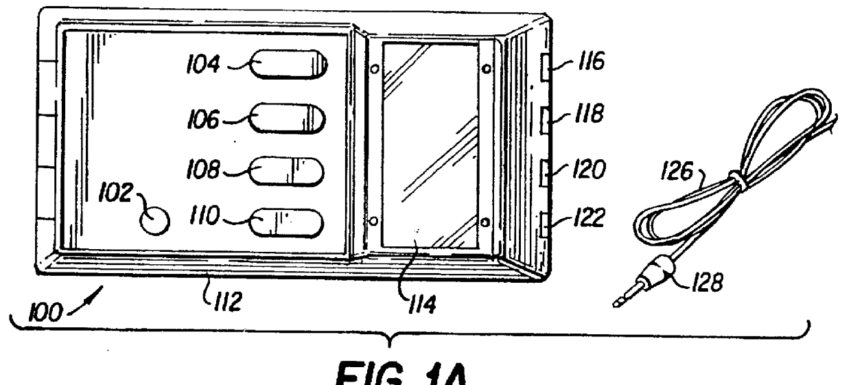
Referring now in detail to the drawings wherein like parts are designated by like reference numerals throughout, there is illustrated in FIG. 1A a top view of the powered muscle stimulator 100 of the present invention. The powered muscle stimulator 100 includes a power switch 102 and four switches 104-110 for controlling the respective outputs of each of the four isolated channels contained in the powered muscle stimulator 100. An LCD display 114 is provided as a user interface. Four output jacks 116-122 are provided at the front of the case of the powered muscle stimulator 100, a separate jack for each of the output channels. Each of the above-described components, together with the circuitry and a nickel cadmium battery system 1208, as well as other components to be described later herein, are housed within the plastic case or shell 112 of the muscle stimulator 100.

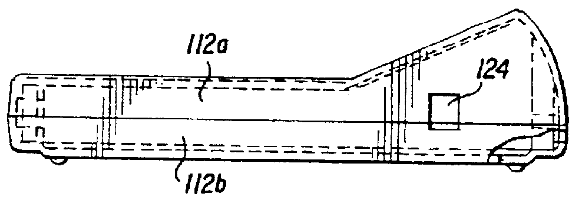
As shown in FIG. 1B, the case or shell 112 of the muscle stimulator 100 may be formed from an upper piece 112a and a ...


PUM


Abstract

A portable muscle stimulator with removable data storage card is disclosed in which the removable data storage card is secured within the power muscle stimulator on specially designed rail guides which prevent the removable data storage card from being inserted to the power muscle stimulator incorrectly and which ensure that the power muscle stimulator is secured in a removable fashion within the power muscle stimulator. The portable muscle stimulator include a multitude of safety features which are designed to prevent injury to the user while at the same time to ensure that the portable power muscle stimulator is easy to use.

Description

BACKGROUND OF THE INVENTIONThe present invention relates generally to portable muscle stimulators for unsupervised personal use. More particularly, the present invention relates to a method of and system for providing a portable muscle stimulator with a mechanism which provides usage monitoring capability.With the increasing application of high technology to medical applications, there has been a trend in recent years to providing as much care as possible as well as sophisticated medical treatment outside of hospitals. That trend has resulted in an increase in the amount of surgery as well as other types of medical treatment, such as rehabilitation services, being performed outside of hospitals in, for example, ambulatory surgery centers or rehabilitation centers, respectively.In order to provide an even more cost effective outcome, technology is being applied to obtain the desired medical outcome with medical equipment that can be utilized in the patient's home. In addition to the ...

Claims


Application Information

Patent Timeline
IPC IPC(8): A61N1/36
CPCA61N1/36014A61N1/36003A61N1/375A61N1/36034
Inventor MCGRAW, MICHAEL B.RUX, WILLIAM A.
Owner HUGHES ELECTRONICS
Why Eureka
Try Eureka