Pultrusion method of making composite friction units

a friction unit and composite technology, applied in the field of composite friction elements, can solve the problems of releasing potentially harmful amounts of it into the environment, affecting the composition and the manufacturing method is not satisfactory, so as to improve the composition and manufacturing method of the brake friction lining

Inactive Publication Date: 2000-05-23
ASCENZ FRICTION & BRAKE
View PDF6 Cites 12 Cited by
  • Summary
  • Abstract
  • Description
  • Claims
  • Application Information

AI Technical Summary

Benefits of technology

It is the primary object of the present invention to provide improved brake friction linings compositions and methods of manufacturing.

Problems solved by technology

Unfortunately, pressure is not the only factor that influences the frictional response of the brake elements.
The materials forming the composition element are the principle unpredictable variables that have the greatest affect on the performance characteristics of the brake system.
However, it was discovered that asbestos is a carcinogenic substance, and that such use released potentially harmful amounts of it into the environment.
These efforts have been frustrated by the many and varied parameters involved, including the range of needs to be met.
However, friction units made by this method are expensive to manufacture and have not been satisfactory, because of their lack of uniformity in performance and durability.
The non-uniformity of results has been found to be caused largely by a non-uniformity of distribution and orientation of the fibers in the matrix.
This not only creates expensive inspection and quality control problems, it can also create maintenance problems, and sometimes even hazardous conditions.
For example, insufficient transverse mechanical properties were found to be a problem among many samples produced by the pultrusion process.
Another problem included excessive voids in some samples.

Method used


Image

  • Pultrusion method of making composite friction units
  • Pultrusion method of making composite friction units
  • Pultrusion method of making composite friction units

Examples


Embodiment Construction

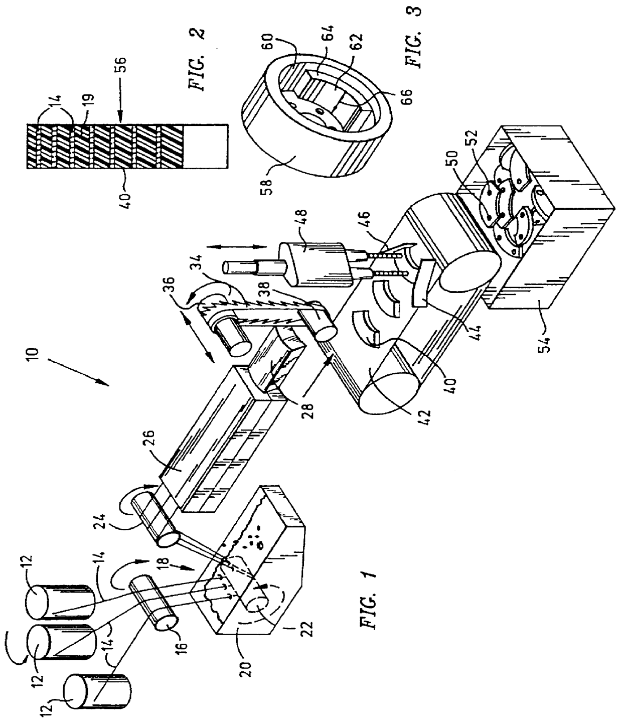
Referring to FIG. 1 of the drawing, there is schematically illustrated the simplest form of an exemplary system for carrying out a the process of the invention for making brake friction units in accordance with the invention. The system, designated generally by the numeral 10, comprises a plurality of creels 12 from which a plurality of strands 14 of an elongated continuous fiber or arrays of fiber are drawn and passed through suitable guide means across suitable guide rollers or bars 16 to and through an impregnating or wetting bath 18 of a suitable resin such as a phenolic resin. The fibers may be in the form of individual strands, woven fabrics, matting, or stitched fabrics of combinations of them.

The fibers or strands 16 are the primary fibers and are coated or wetted by a resin in any suitable manner. In the illustrated embodiment they pass into or through a bath of a suitable liquid resin contained within a reservoir 20 for wetting or impregnating the fibers or strands. They c...


PUM

PropertyMeasurementUnit
angleaaaaaaaaaa
lengthaaaaaaaaaa
lengthaaaaaaaaaa

Abstract

A composite friction unit includes a three dimensional composite body formed of a substantially uniform array of predominately glass strands of primary reinforcing fibers in matrix of phenolic resin material, the reinforcing fibers distributed throughout the body in a predetermined uniform distribution and orientation, and a substantially uniform array and distribution of secondary fibers extending transverse to the primary fibers thereby forming a friction unit having a predetermined size and configuration and uniform distribution and alignment of fibers throughout.

Description

BACKGROUND OF THE INVENTIONThe present invention relates to composition friction elements and pertains particularly to improved friction units and method and composition for making same.A friction brake is basically a pair of friction elements, one rotating and one stationary, brought into engagement to produce a friction force measured as brake torque for either slowing or stopping the rotating element. Brakes are designed so that the brake torque is somewhat proportional to the input force used to engage the elements. Unfortunately, pressure is not the only factor that influences the frictional response of the brake elements. Friction effects between friction elements cause friction force and brake torque to vary with engaging pressure, speed, and temperature, and to depend upon deposited interfacial film for stability.The rotating element of a brake system is usually a steel disc or drum, and the stationary element is usually a composition pad or shoe lining. The materials formin...

Claims


Application Information

Patent Timeline
Patent Type & Authority Patents(United States)
IPC IPC(8): B29B15/10B29B11/16B29B15/12B29C70/02B29C70/04B29C70/00B29C70/52B29C70/54D04H3/08F16D69/02
CPCB29B15/125B29C70/025B29C70/521B29C70/525B29C70/545D04H3/08F16D69/026B29C70/52Y10T156/1084B29K2705/10B29K2707/04B29L2031/16B29L2031/7482B29K2061/04
Inventor BOOHER, BENJAMIN
Owner ASCENZ FRICTION & BRAKE
Why Eureka
Try Eureka